Build Thread: MAC Performance Rocketry 4" Extended Villain

The Rocketry Forum

Help Support The Rocketry Forum:

This site may earn a commission from merchant affiliate links, including eBay, Amazon, and others.

patelldp

Well-Known Member
Joined
Jan 23, 2009
Messages
5,647
Reaction score
101
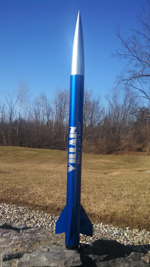
As I alluded to in my 3" MAC Arcas build thread, I picked up my very own 4" MAC Villain from Mike. The kit is typically 66" long (27" booster, 20" payload), but I custom ordered it 21" longer with a 48" booster. This will permit me to use motors like a 54-2550 with an adapter or a 76-6000 someday. The kit looks great at the stock length, I just wanted to have a little more flexibility. A few messages between Mike and myself and I had my custom length kit...and you can too! Give Mike a ring or an email and he'll work with you!!!

Just to start, here's the run down on the rocket (from the MAC Performance Rocketry website, www.macperformancerocketry.com

Specifications:

Length: 66 inches (87" for my kit)
Dual Deployment
Motor Mount: 75mm
Approximate Weight: 64 oz (TBD for my kit)
Will fly on I through L motors (Mike texted me to correct me...my custom long kit will take an M...)

Content of Kit:

27" x 4" canvas phenolic booster tube (48" for my kit)
20" x 4" canvas phenolic payload tube
75mm x 16" kraft phenolic motor tube
5:1 Pinnacle nosecone -- 19 1/2" exposed
(3) 1/8" G10 beveled fins
3/8" fore C ring with integrated shock cord attachment system that includes 9/16" tubular nylon booster harness
1/4" mid C ring
3/8" aft C ring with a step machined in the OD to double as a thrust plate
3/8" altimeter bay bulkheads with machined step to engage coupler
4" x 1" switch band
8" long machined XX phenolic coupler/altimeter bay
Altimeter bay includes: (2) aluminum 1/4" all thread rods,
3 1/2" x 6" canvas phenolic altimeter sled with standoffs
Includes all necessary hardware (does not include motor retainer)
Assembly instructions included

Villain_Out_1024x1024.jpg


Next post: Pictures of my kit and the adhesives I'll use in the build!
 
Last edited:
First picture of my own is of the kit as I received it:

Kit_Parts.jpg

Once again, everything just fits. Mike heard my initial "beef" with the Arcas and made his fin bevels more aggressive and they look great. Centering ring fits are perfect, fin slots are the perfect length, and Mike even lengthened the shock cord leader to extend beyond my 48" booster tube. The attention to detail is incredible.

I also requested a few extras with the kit:

Extras.jpg

The extras are:

2 - 20' x 9/16" tubular nylon shock cords
2 - 1515 rail buttons (now where the heck did that other bolt go?)
2 - aluminum ejection canisters

The canisters look GREAT, the buttons are quite low profile, and the shock cords will do very nicely! I'll highlight these a little more closely when I get to that portion of the build.

How it's all going to get stuck together:

Villain_4_Build - 4.jpg

30 minute hobby store epoxy for tacking and minor fillets, Glenmarc RocketPoxy for primary filleting, and Rocketry Warehouse lightweight 2-part expanding foam for the fin can. I used the foam on the Arcas and it allowed it to survive a landing without a chute, so I'll use it here as well!

Next up is the installation of the shock cord anchor in the upper CR!
 
One of the best features of the MAC kits is the shock cord mounting method. Other manufacturers suggest and employ a Kevlar strap epoxied to the motor mount. That method works just fine, but the method employed by MAC is pretty slick and is certainly solid. The method uses three parts, a shock cord leader with loops sewn in both ends, a steel pin, and a CR with a precision routed slot for the cord and pin:

Shock_Cord_Mount 1.jpg

Here's how it goes together. You pull the cord through from the top of the CR, slide the pin through, slather epoxy in the slot, then pull the cord through. The pin sits in the groove, which then gets a little more epoxy to keep it together. The epoxy really isn't necessary, it just keeps things from shifting. All of the strength is derived from the pin's engagement with the ring.

Shock_Cord_Mount2.jpg

Here's the assembly epoxied together. Be sure to keep from getting epoxy on the cord when you install the ring on the motor mount tube and subsequently into the main body tube by pulling the cord back through the MMT. It won't be the end of the world if you do, but it's just best to keep it neat. I'll cover my methods when I get to that point.

Shock_Cord_Mount 3.jpg

Next up is the assembly of the drogue-side altimeter bay while we wait for the cord mount to cure.
 
Another one of the beauties of these kits is the completeness of the altimeter bay. You get stepped bulkheads, all the necessary hardware including aluminum threaded rods, a sled and sled mounting pieces. In addition to that, I received the AWESOME addition of the aluminum charge canisters which are a wonderful touch to the kit.

First piece of hardware to go into the bulkhead is the eyebolt. I actually subbed out the stock bent wire eyebolt for a SS welded eyebolt from Fastenal. I did this for 2 reasons...I wanted the strength insurance on the drogue side due to the potential for violent deployments at apogee and my brother works for Fastenal and gets good deals. The 3" Arcas uses the stock eyebolts which is fine, it would really take a pretty traumatic event to open the eyebolts.

This picture is an exploded view of how I have ensured that eyebolts never twist themselves out of a bulkhead for 10+ years of flying. On the outside of the bulkhead is a 1/4" nut, a small washer, and then the bulkhead. On the inside of the bulkhead is a fender washer, a split washer, and then a regular nut. The split washer is key as it applies tension to the whole assembly when cranked down and discourages disassembly.

Altimeter_Bulkhead1.jpg

Next up is the aluminum threaded rod. This is done in the stock fashion as it's how I've been doing it for the same 10+ years. On the outside of the bulkhead is a nylock nut, then a washer, then the bulkhead. On the inside is a washer with a standard nut. Grab the all thread with a pair of soft jaw pliers, thread the nylock nut on until the all thread is fully engaged in the nylon, then tighten down on the inside nut until the whole assembly is tight.

Altimeter_Bulkhead2.jpg

Next step was to eyeball the location of the charge canisters and euro terminals. After I eyeballed and marked the bulkhead, I rough measured for symmetry and popped holes with my drill press. I actually undersize the holes ever so slightly so that the screws self tap into the wood, then back them up with small washers and nuts.

Altimeter_Bulkhead3.jpg

Lastly, here's the bulkhead placed in the coupler. Only thing left to do on this bulkhead is to pop 2 holes for wires to pass through and then disassemble it all and apply a coat of epoxy. Normal people do that before doing what I just showed you, but who's normal these days?

Altimeter_Bulkhead4.jpg

That's all for tonight. I have a business trip to NJ tomorrow followed by a birthday celebration, but eventually i will start measuring and installing the centering rings onto the motor tube.

Stay tuned!!!
 
Dan you need to use a 4 inch to 3 inch aeropack tail cone retainer. It would look sick and get Ya better altitude with style.

Eric

Hey Eric,

I thought about it, but I have this lathe thing in the basement to put to use. My plan is to make an aft plate that will slip over the motor case and have a slight recess cut in it to make way for the external spiral ring. Three 10/24 bolts will hold it tight against the aft CR, clamping the motor to the aft CR. The OD will have a bevel on it that will resemble a slight boat tail. Total cost will be zero as I have the material and all the time in the world to machine it...hah...
 
So, maybe I lied a little bit...got another minor step done during the intermission of the Tampa Bay vs. NY game. Don't want to miss game time, it's an exciting and high scoring game!

I completed the initial tacking of the fore CR now that the cord mount from the previous step had cured. The first step with every glue step is to appropriately scuff all surfaces. I used a small piece of emery cloth (~50-60 grit equivalent?) to scuff the circumference where the ring will go:

MMT1.jpg

Next step is for the OCD individuals among us. The CR's that come with the kit are snug on the MMT, however I like to take this extra little step to ensure it's perfectly recessed from the end of the tube. No real reason to do this as it will be undetectable when the rocket is fully assembled, but I'll know it's there...

MMT2.jpg

After spacing the ring correctly, it looks like this. All is right in the world...

MMT3.jpg

There's two ways to attach the ring. The first would be to apply a bead of 30 minute epoxy to the end of the motor mount tube prior to the previous spacing step and push the ring on using the spacers as depth stops. That's probably the best way to do it with regards to strength, but it can be a bit messy and is probably not necessary. Because of the tight tolerances of these parts and the fact that porous materials are used, I decided to set the ring in place and then wick some super glue in there to lock it in place. All this really accomplishes is to hold the ring in place for the next step...adding RocketPoxy fillets to both sides.

MMT4.jpg

Next post will be to further educate you on the Canvas Phenolic tube!
 
Here's a few pics to show you exactly what this tubing is. It's really the canvas equivalent of the G10 tubing we all used to know and love from Performance Rocketry. It's convolutely wound and has an almost unnoticeable seam on the outside because it is ground to the correct outer diameter. In order to finish the tube, all it needs is a few coats of high build primer and light sanding and you're good to go. Life is good without spirals!

Tube_Close_Up1.jpg

As you can see, the tubing cuts very cleanly without any cracking, chipping, or delaminating. Here's a close up of the inside of the tube with the slot in view.

Tube_Close_Up2.jpg

Super high quality. This build should hopefully stress it pretty reasonably...a 6000 Ns motor in a 4" airframe this lightweight should result in some respectable velocities!
 
I mixed up a small batch of RocketPoxy prior to hitting the road this morning. I filleted the fore side of the CR with a decent bead around the MMT/CR junction. This is where all of the strength will come from and why it was okay to tack the CR with Super Glue.

MMT_Fore_Fillet.jpg

Once this cures, I will spend a little time locating the middle centering ring and tack that in place. That CR will get the same fore filleting treatment. Just like my Arcas build, this fin can is going to be filled with the 2-part expanding foam shown in a previous post. Because of this, the mid CR is going to be spaced about 1/2" above the fore end of the fin tab to allow the foam to flow around the fin and lock it in from all directions.

Next post will be a pictorial on my time with some rings, some tubes, and a tape measure!
 
If I fly it on a 76/4700 or 76/6000 at LDRS, 1515's are most common at the M pads. It's really 6 vs 1/2 dozen.

Another good reason is that oftentimes the 1010 pads are more popular and will fill up quicker, and the 1515 pads will be sitting there with no one using them. :wink:
 
Another good reason is that oftentimes the 1010 pads are more popular and will fill up quicker, and the 1515 pads will be sitting there with no one using them. :wink:

Hint: 1010 buttons work on 1515 rails!
 
Okay, back in the saddle for some minor steps involving placement of the middle CR. Because I will be using 2-part expanding foam to make a solid fin can assembly, I am spacing the middle CR a short distance from the fore end of the fin tab. If I were doing epoxy fillets internally, I'd make the tabs butt against the CR and fillet that as well. Because of the foam, I am putting in the space to permit the foam to flow around the entirety of the fin to fully encapsulate it.

First step in this process is to locate the fore and aft ends of the fin slots on the MMT. In this case, there's quite a bit of space between the aft of the fin and the aft tube edge. If I weren't foaming the fin can, I would likely be inclined to add a CR to this design to sandwich the fin in CR's. Probably overkill, but not necessary with the foam (which is likely also overkill).

Villain_4_Build - 1.jpg

Once the tab is marked (the fit of these CR's is so nice that I was able to slide the ring up and trace my line...no wobble!), I decided on the location of my ring. I bumped it up ~3/8" above the fin tab and tacked it with Super Glue.

Villain_4_Build - 2.jpg

Next step is to fillet both sides of this ring, the underside of the upper ring (and shock cord mount backside), and then insert the assembly into the body tube. Next steps will start to get more exciting...
 
Another highly exciting step! After having tacked the mid centering ring with Super Glue and allowing that to cure, the next step is to apply fillets to both sides of the CR. If you're smarter than me, you wait until both CR's are on to fillet both sides at the same time, really just saves the time of an extra epoxy cure.

Villain_CR_Fillets - 1.jpg

Next step in this drawn out documentation will be prepping the motor mount tube and inside of the main body tube for motor mount installation. Sanding and cleaning parts is paramount at that step, so I'll do my best to document how I do it for you all. That should come later today at some point. In the mean time, I've been machining a nozzle for a 76/2500 motor...
 
ImageUploadedByRocketry Forum1432409371.359696.jpg

Divergence section complete for my 75/2500 nozzle. Not really related to this build, but it will likely fly in the Villain at some point.
 
Dan is that for the old Kosdon case? If so I'm glad to see it get air born again.

Eric

Maybe, I actually have a bunch of tubing on the way. I am thinking of turning the Kosdon case into a 1700 or even a 1200 case. Need to get my steady rest done so I can start making chips on cases!

Finished nozzle pics:

ImageUploadedByRocketry Forum1432413940.727404.jpg

ImageUploadedByRocketry Forum1432413956.613802.jpg
 
Final CR fillet is in place. I'm going to let everything cute overnight and then install the motor mount first thing in the morning.

ImageUploadedByRocketry Forum1432439535.361275.jpg
 
As promised, I installed the motor mount today. Here's the steps that I take to make that happen!

Step 1 was to go over all of my completed fillets and the field in which the foam will expand to with some emery cloth. Again, 50-60 grit sand paper will work well. You want plenty of surface area for that epoxy to stick to.

Villain_MMT_Install - 1.jpg

After all of the sanding is complete on the MMT assembly, time to turn your scuffing skills to the inside of the body tube. Again, emery cloth is used to scuff all of the areas where epoxy or foam will contact and cure on.

Villain_MMT_Install - 2.jpg

Now that everything is sanded, it's time to figure out how we're going to get epoxy where it needs to go. For the foremost CR (the one with the shock cord mount), epoxy will be applied at a depth just short of the final resting place of the ring so that when we push the assembly in it will pull the epoxy with it, resulting in a bond to the body tube and a fillet on top. To get the epoxy at the right depth, I'll use my ever-so-versatile 1/2" oak dowel. This thing is great for epoxy application and propellant packing. It has some miles on it, but it's pretty much sealed with HTPB and epoxy at this point.

I laid the MMT next to the tube at the correct depths, then placed my dowel beside that. I make a sharpie mark where the dowel exits the tube when placed at the correct depth. I then put some epoxy on the dowel and put my hand at this mark, using my thumb as the depth stop. The result is a perfect ring of epoxy just aft of the final location of that CR.

Villain_MMT_Install - 3.jpg Villain_MMT_Install - 5.jpg

Next up is my method for applying epoxy to the mid CR!
 
So, how can we get a fillet between the mid-CR and the body tube? It's impossible for me to somehow apply a ring of epoxy on the ID of the body tube and have the mid-CR form a fillet when pushed in because the fore-CR is only a few inches ahead of it. This is what I came up with:

Step 1 is to make sure that you keep your shock cord anchor from getting epoxy on it during these semi-complex steps. What I do is I pull the cord down through the motor mount until it's semi-taught, allowing for the sewn loop at the top of the MMT to stick up a little bit. I then tape the cord to the inside of the aft of the motor mount to keep it there and to stop it from flopping back. I then gather the rest and tape that up so it's shorter than the full length.

Villain_MMT_Install - 4.jpg

After you have smeared epoxy in the main tube for the fore-CR as displayed in the previous post, take some more epoxy and smear it just above the mid-CR as such:

Villain_MMT_Install - 6.jpg

Working semi-quickly, I then push the motor mount into the main tube, moving a little slower as the fore CR reaches the epoxy applied previously. The epoxy acts as a bit of a lubricant and you can risk pushing it in too far, ruining the fillet. In the case of this kit, I placed the aft-CR on the MMT flush with the tube, set it on my concrete floor, and smoothly slipped the main body tube over the MMT until the tube engaged the stepped aft-CR/thrust plate.

Heres a view down the tube (albeit a poor one) that shows the fillet that is formed.

Villain_MMT_Install - 7.jpg

The key to all of this? A vibratory parts sorter. After all of the above steps, I place the assembly on my vibratory base to promote flowing of the epoxy above the mid-CR. The epoxy is pretty viscous and will flow a little, but the vibrations definitely help move it quickly. I cannot confirm that this works as it's completely encapsulated by the tube and will never see the light of day (if the rocket has a nice life...), but looking at the fore-CR it certainly flows considerably.

Villain_MMT_Install - 8.jpg

One final note. You'll see the shock cord leader hanging out of the tube. After the assembly reaches its final destination, I undo the tape job explained above and push it through the MMT and out the top of the tube. I then hang it over the opening and put a quick link through the loop, holding the cord taught within the tube. This will make sure that the cord doesn't somehow get epoxy on it and stick out past the ID of the motor tube, interfering with motors longer than the motor mount tube.
 
Now that the major internal assembly is done, what do you guys think so far? The participation is pretty low aside from my documentation, should I continue?

I have a few questions for those of you lurking out there:

1. Are you learning anything by my doing this?
2. Are there any questions that you have about this or other MAC Performance kits that I can help with?
3. Is this thread piquing your interest about the new line of kits?

I'm open to criticism, comments, suggestions, etc.!
 
Did you epoxy the aft-cr in post #23 or is it still loose?

I am enjoying your build thread.
 
Did you epoxy the aft-cr in post #23 or is it still loose?

I am enjoying your build thread.

Still loose. I'll be foaming the fin can, so the CR stays off until after the fins are in, filleted, and foamed.

Thanks!
 
Now that the major internal assembly is done, what do you guys think so far? The participation is pretty low aside from my documentation, should I continue?

I have a few questions for those of you lurking out there:

1. Are you learning anything by my doing this?
2. Are there any questions that you have about this or other MAC Performance kits that I can help with?
3. Is this thread piquing your interest about the new line of kits?

I'm open to criticism, comments, suggestions, etc.!

1. Yes - specifically leaving the gap between the fin tab and the mid CR for the foam.
2. Don't know if you can answer this, but how does the canvas phenolic do with wood glue? I prefer to not use epoxy unless I absolutely have to.
3. Definitely.
 
1. Yes - specifically leaving the gap between the fin tab and the mid CR for the foam.
2. Don't know if you can answer this, but how does the canvas phenolic do with wood glue? I prefer to not use epoxy unless I absolutely have to.
3. Definitely.

That's interesting. I have never tried, but assuming that you scuff the surface I would think it would work. It's not nearly as porous as the wood CR's, if at all, so I don't know.

Wish I could be more helpful. Maybe there's information online?
 
nice work Dan. I used a similar technique for centering ring fillets on my 3" DYOK build and I assume it worked as well :)
 
Back
Top