Telemetrum setup questions

The Rocketry Forum

Help Support The Rocketry Forum:

This site may earn a commission from merchant affiliate links, including eBay, Amazon, and others.

V2rocketeer

Well-Known Member
Joined
Jul 29, 2012
Messages
211
Reaction score
0
Hi All

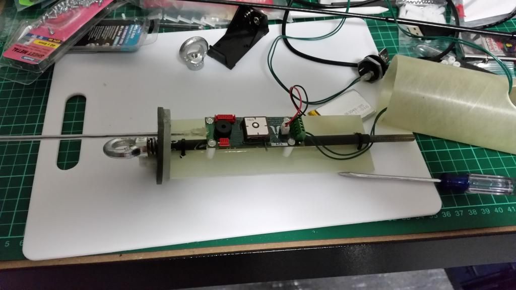
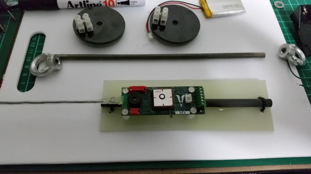
I'm installing a Telemetrum 1.2 into a MD 54mm bird that will be pushed hard with big motors.
My ebay has a central threaded rod to hold the ends together. To avoid or at least reduce the antenna of the
Telemetrum from coupling with with the rod I have epoxied a section of carbon tubing that should encase the
threaded rod. Yes this will in some way block some of the RF but I think that locating the altimeter with a majority
of the antenna poking out into the next bay should assist with that. I was under the impression that the Telemetrum
had to be antenna up in its installation. I see in the AltOs configure Altimeter that there is an option to configure the
altimeters orientation. Can the Telemetrum be mounted upside down? It suits me better as I can run the antenna
into the drogue bay which will not have a drogue and have less to tangle with than in the main bay with the chute.
So my 2 questions are.

Is there any problem running the Telemetrum as shown below with the threaded rod covered by a carbon rod ?

Can the Telemetrum V1.2 be mounted upside down?

I will do some ground testing of the RF signal from the Telemetrum but was curious if anyone else had tried this?

73

Chris vk2icj

 
Last edited:
Yes the Telemetrum can be mount upside down, but you have to setup it with this position ....you have an option in the setup software ( altOS ) for the antenna orientation
 
Is there any problem running the Telemetrum as shown below with the threaded rod covered by a carbon rod ?

I'm probably missing something but I don't see why having the steel rod inside the carbon rod will improve anything. It would be interesting to see the results of a careful comparison of three conditions. 1.) Antenna in the clear 2.) Antenna next to bare steel rod 3.) Antenna next to carbon rod with steel rod inside.
 
Thanks guys

Usually I try to keep my antennas away from steel rods n the like in my builds. This one has to be close.

Is there any problem putting a dabble of hotglue at the PCB board where the antenna wire is attached? I have tested the hotglue with my ohm meter and found it to have zero conductivity I just want to add a little strength there because the plastic covering of the antenna will be inserted in and out of the bulkhead each time I use it. You can see I hotglued the other side but would like to dabble a bit on this side too.

73 thanks for the help

 
As always, doing ground testing is the key to knowing whether things will work in flight. We report the received signal strength, so if you can get a mile or so of clear air between TeleMetrum and the ground station, you can see what effect any of your changes will have on the signal.
 
If you simply want to isolate the threaded rod, you can use heat shrink tubing. I usually do is in my av bays. Since carbon tubing is electrically conductive, it may not help that much.
 
Just curious... Would replacing the threaded rod with threaded nylon be a viable option? I'm not sure how much force you're planning to put on it but that was the first thing that came to my mind. Also, I think they make threaded G10 as well if nylon is too weak. If those would work then you would get rid of the interference completely.
 
Conductive rods close to and inline with the antenna is just about the worst thing you can do for the signal. That said, you will probably be OK for normal sport flights, but as Keith said test at the range you expect to reach (up in the air as well as down-range).
 
Thank you Keith and others.

I'm familiar with RSSI being also into RC aircraft and FPV. Which is sort of where I got the idea for the carbon rod. Carbon is a conductor yes but is also a great RF shield. Usually this is a problem but I thought if it shielded the threaded rod in the middle RF wise then it might stop the RF problems you usually get with having an antenna in line with a metal object. I did some basic RF tests tonight and did not notice any notable RSSI difference between with the shielded rod and with no rod or threaded rod at all. That however was at a distance of less than 200 meters. This is a minimum diameter build and the threaded rod is what will keep the the booster connected to the ebay and then the ebay to the main chute and nose cone. It will need some strength. I was thinking of ditching the Telemetrum all together and putting a BRB in the nose cone and a RRC3 in the ebay but I'm pretty keen to use this Telemetrum on this bird as it will be my highest flying bird at Thunda.

20150204_211158_zpslwzhahie.jpg
 
I've done lots of ebays just like the one you're building and they work fine. Using CF tubing won't change the effect of the steel threaded rod though; it's all conductive, so it looks like one piece of wire to the transmitter. About the only thing you might consider is moving the TM closer to the end of the ebay so you get less coupling to the conductive bits. Current TeleDongle and TeleBT receivers are pretty reliable down to about -100dBm, so a few measurements at a known distance should give you some idea of the maximum range as the signal will drop by a bit more than 6dB per doubling of distance.
 
You will have a difficult time finding a threaded fiberglass rod smaller than 3/8" O.D.

A potential solution would be to machine a threaded metal rod with socket that you can epoxy fiberglass rod inside the bore. The metal would be in the endcap and the stock non-machined rod would be in tension which is the best loading position. This is analogous to a swaged end on a wire rope.

It should be a lot cheaper too. The part could be made cheaply on an automatic screw machine, but in quantities of 500 or more. Cost would probably around $1-$2 each in those quantities.

A poorman's way would be to take a thread 1/4" spacer at least 1/2" long.

1.) Ream out half the internal length to a few thousands over the OD of the fiberglass rod.

2.) Get a PTFR or PE plastic screw that is threaded 1/2 the spacer length and thread it fully into the threaded end to prevent the thread from being fouled by epoxy.

3.) Cut the fiberglass rod to length and epoxy into one spacer.

4.) Check fit length inside e-bay with out epoxying in second end. Shorten FG rod if required. Epoxy second end on FG rod.

5.) Holes in endcap should be a few thousands larger than the space o.d.

6.) Length of assembly should have the ends of the space just below the surface of the e-bay end plate surfaces.

7.) Use SS screws and washer to pull into compression.

You could also simply epoxy on a socketed cap on one end if you so desire.

Bob
 
Back
Top