The creation of the CinerocDV Camera.

The Rocketry Forum

Help Support The Rocketry Forum:

This site may earn a commission from merchant affiliate links, including eBay, Amazon, and others.
A quick update.

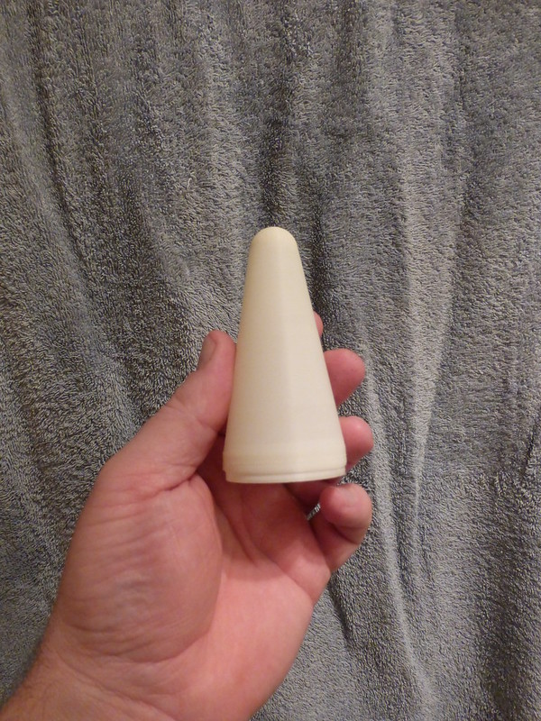
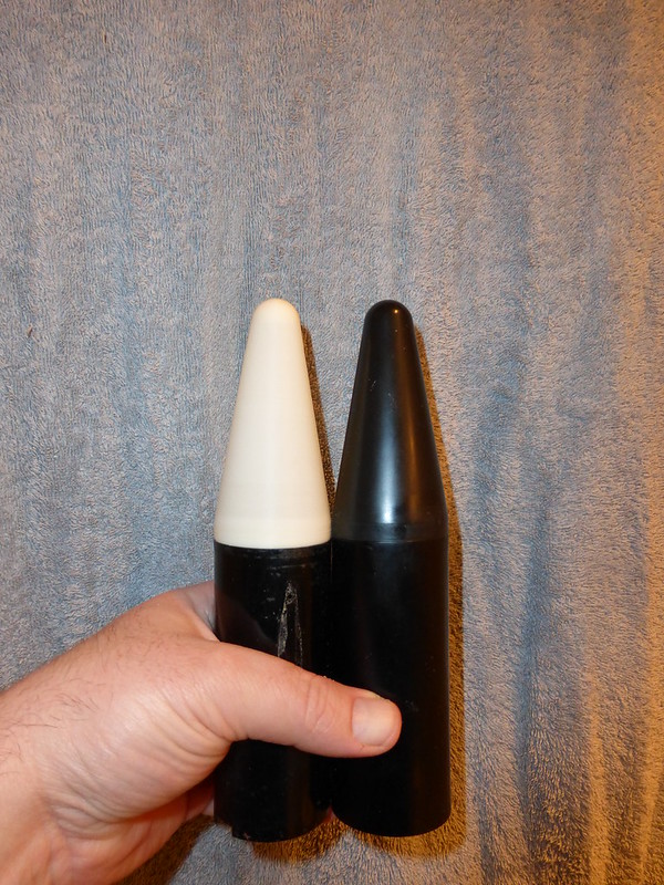
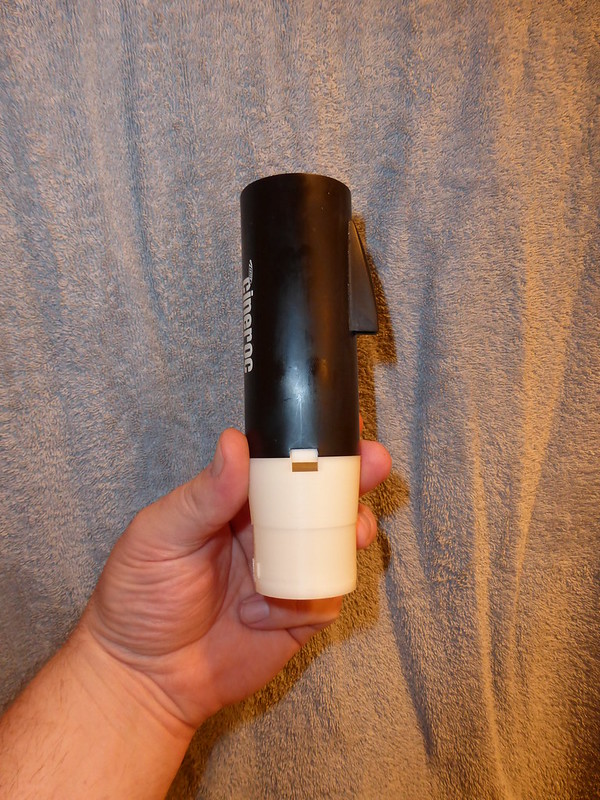
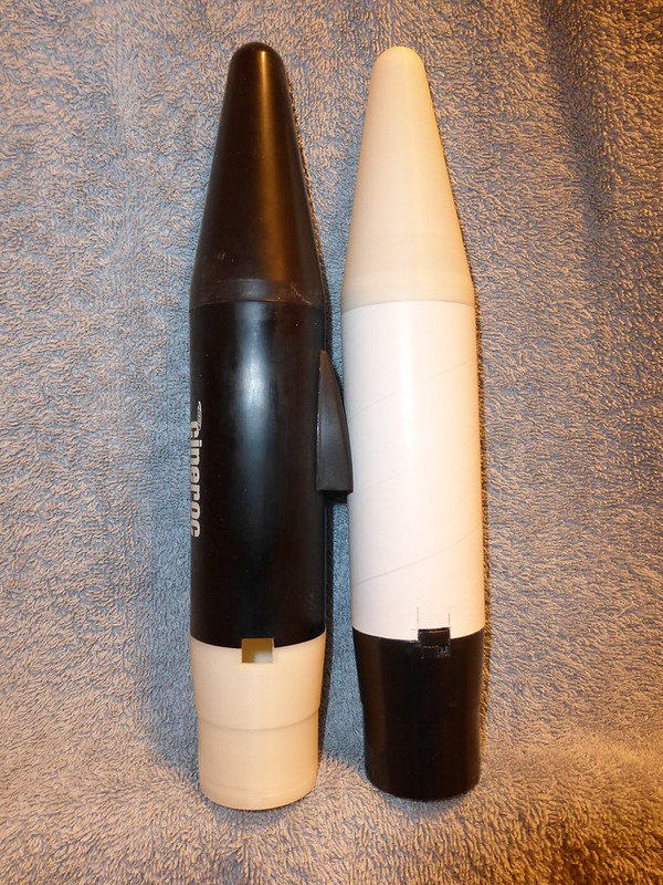
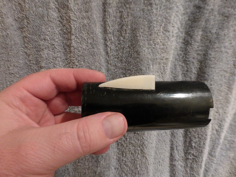
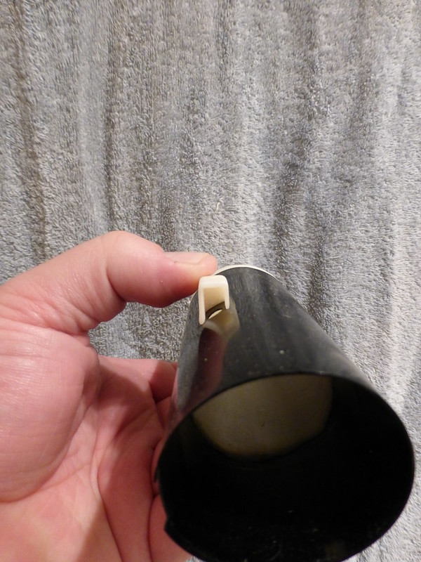
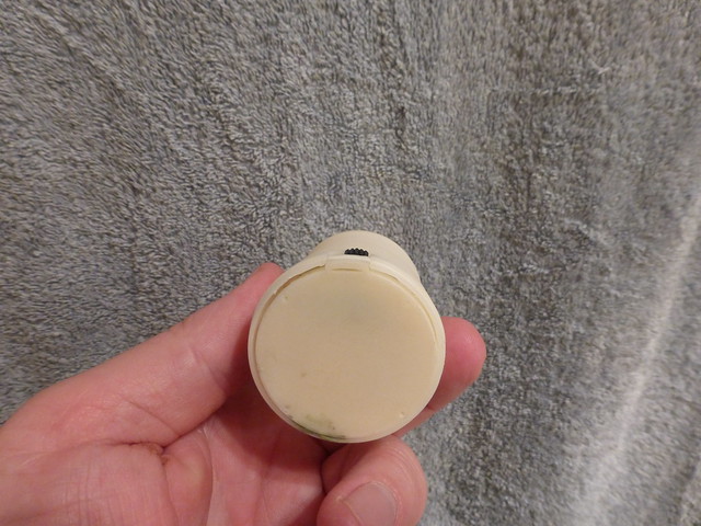
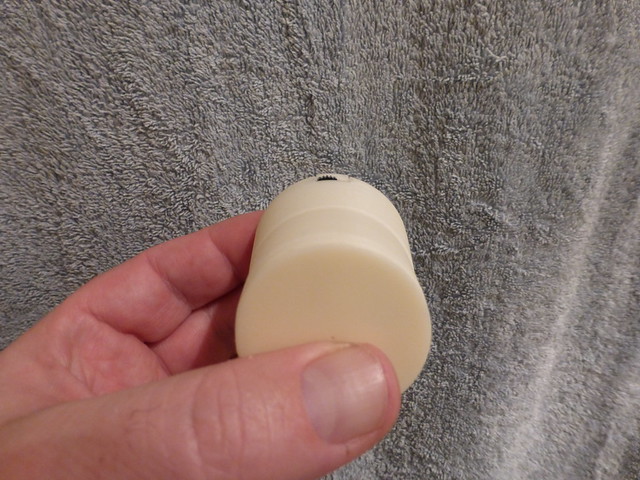
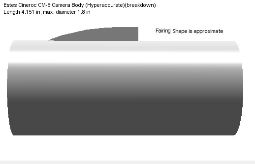
Nosecone was printed today in ABS (mostly to determine print settings). The model was still pretty rough; there was a small offset where the rounded tip met and no shoulder. We have a few small tweaks to try but the entire cone printed and everything seems structurally sound. I have revision 2; a more accurate model complete with shoulder and fully filled tip that smoothly transitions to the cone. I will be in tomorrow morning doing some work and will attempt a print.

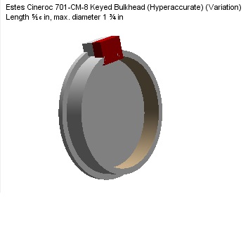
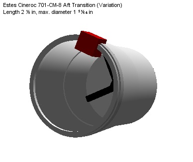
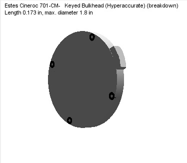
The bulkhead should be ready to print. We still don't have the lower transition, but that shouldn't take too much.

With the direction this thread has taken, it might be a good idea to move it elsewhere on the forum. Any thoughts?

Doug
 
Thanks for the update Doug!

I'm looking forward to seeing it and getting the CinerocDV built for real.

With the direction this thread has taken, it might be a good idea to move it elsewhere on the forum. Any thoughts?

Perhaps move it to LPR or Rocketry Electronics and Software (it is part of a camera system).

All The Best!
Jim
 
Update:

All parts are modeled. Screenshots are posted below for inspection. There are some features that are not exactly easy to print (overhangs) that will need some coaxing to get right, but I think that we'll get it figured out.

View of the aft transition without a bulkhead showing the notch from the inside.
Cineroc-AftTransition.png

Aft transition with bulkhead in place.
Cineroc-AftTransitionAndBulkhead.png

Looking through the notch with the bulkhead in place.
Cineroc-AftTransitionLookInSlot.png

Detail of the reinforcement in the bottom of the transition. I think it might be a bit overkill.
Cineroc-AftTransitionReinforcement.png

Doug
 
You have done an awesome job on this. I have alway wanted one. The Astrocam is such a poor substitute.
 
WOW Doug!

That is looking AWESOME!

I have a possible solution to the overhang... Is it possible to blend the inside edge of the support ring with the inside of the transition cone?

Thanks!
Jim
 
WOW Doug!

That is looking AWESOME!

I have a possible solution to the overhang... Is it possible to blend the inside edge of the support ring with the inside of the transition cone?

Thanks!
Jim

Jim,

That is possible, but now you're talking a LOT of extra plastic/mass/time to print. I have a few ideas that I can try if needed. I'm heating the printer up right now for some test prints...

Doug
 
To the readers...

One thing that I noticed this morning on the dimensional drawing put out by Mike Jerauld, was a little disclaimer "All measurements are appoximate and are FOR REFERENCE ONLY". Ouch!

Mind you, since the drawing didn't have the shoulder for the camera body's support (on the nosecone, or on the leading edge of the aft transition), I had measured them using my calipers, so they are as accurate as I can tell. I've tested the Cineroc's nosecone with a piece of the body tube used in the D-Region Tomahawk kit from Estes, and it fits... It will need reinforcing (with thin CA) and sanding to make it strong and stable, but it's the only match I've been able to find in the time I've spent looking for a suitable replacement for the camera body's body tube.

However, I had my doubts about the aft shoulder of the aft transition. So, I looked at the file, and sure enough I had gone with the defaults that OR has for a BT-60's interior diameter (1.595"). If someone were to recreate my design exactly, they might find that it has a tight (or perhaps too tight) of a fit. I measured my Cineroc, and found that the shoulder wasn't 1.592" tapering to 1.571" as indicated in the drawing. My measurements are 1.595" tapering down to 1.572" by my calipers. I've notified Greg, and Doug, and corrected the .ork file.

I've also modded in a way of eliminating the undercut on the rim that supports the bulkhead.

On the real Cineroc, at the back end of the aft transition's conical section, you'll see a ring (about 1/16" wide) that *could* be a different diameter than the rest of that section. I've looked into that, and it appears to me to be a result of the molding process, and not a deliberate feature. I've not added this to the model for that reason.


Mind you, I was typing this up as Doug was warming up his printer...

Stay Tuned!
Jim
 
Last edited:
I just got back from trudging through the snow to and from the school to pick up the last printed part for the day. I now have a set of what we'll call version 0.9 for now. BT-60 fit is very nice on the tube I have. I did taper it as K'Tesh mentions above. It starts out just a bit loose and snugs up very nicely as it meets the transition.

This is the first time I've printed with ABS instead of PLA; they are different beasts and behave just a bit differently. The first cone I printed Friday morning was atrocious; run two of the cone from this afternoon looks pretty darn good. It is a little rounded where the shoulder meets the cone, but all other aspects are almost perfect. The bulkhead was a trial of the second run of settings; it is better in most respects but the model wasn't quite perfect and the holes are mostly disappointing. The transition just got off the printer about 30 minutes ago. I had a little problem getting the support material off; there was a bad setting when I sliced the model. This will be corrected for the next printout.

Bulkhead fit was spectacular. It is just under the diameter of the opening and fits flush with the top of the transition shoulder.

I am getting a bit of faceting on the sloped portions of the cone and transition. I haven't found any way to reduce this yet, but it would sand/fill easily if one desired. I'll keep looking for an answer on that puzzler.

On to pictures:

The happy family in natural ABS.
IMG_20150131_221529.jpg

Interior of nosecone and bulkhead in the transition.
IMG_20150131_221610.jpg

Looking down into the transition. The plastic on the sides was support for the centering ring / support for the bulkhead. Bad printer setting led to it sticking on far more than it was supposed to.
IMG_20150131_221632.jpg

Flat interior of the nose tip. Tip is solid. Do you want a small pilot hole in this area for a screw?
IMG_20150131_221645.jpg

BT-60 with the transition on. Beautiful fit; a little rough on the shoulder interface because of supports I had to cut off with a knife. They will be better next time.
IMG_20150131_221755.jpg

That's it for tonight. I at least need to print out a new bulkhead and will then send these off to be tested with the camera. I will probably try to tackle the camera tube (likely minus the hood) this week if time permits or next weekend.

Doug
 
Ooooohhh! Pretty! :clap::clap::clap::clap:

Those look Great!!!

As so far as the holes go, again, they're optional so they could be just marked, then drilled out by the end user before the parts are screwed together. I'd say no to the hole in the nosecone. The original didn't have that hole by default, and once it was drilled, they recommended that the user keep the screw eye in place (prevented light from getting in and messing up the film).

I wouldn't try to print the camera body, that would likely be more trouble than it's worth. Again, the D-Region Tomahawk is what I'm planning using for the camera body, unless I can find another suitable tube to the job. Eventually the camera shroud will need to be done, but outside of the dimensional drawing, and the photographs, I don't have a better way of showing what's going on there.

I think we're closing in on the goal!

Thanks!
Jim
 
Last edited:
To double check the camera body, I tried using a few different body tubes from rockets that are close to the camera body's outer diameter.

The Estes Pro Series Terrier Sandhawk/Python Missile body tube is a very loose fit, and wouldn't work.
I can actually slide the Cineroc camera body inside the Semroc Omega's simulated camera body (but the shroud prevents it from being able to pass through it).
I tried a couple of D-Region Tomahawk body tubes, and like before, the fit is tight, and would be a good substitution for the actual plastic camera body.

I did discover that for an exact copy of the inner mechanisms of the Cineroc, the shoulder of the nosecone does need to be .125" long, otherwise it will be pushed out by the bulkhead that supports the battery pack.

A check on the length of the camera body itself has mine at 4.161" for the working one, and the backup (three small teeth marks from a puppy) is 4.141" (between 4 9/64" and 4 11/64"). Compare that to the dimensional drawing's 4.375" (4 3/8" (aka 4 24/64"))

I decided to check the exterior dimension to see what (if anything) didn't agree with the dimensional drawing... Well, there's quite a few of them...

Here's the dimensional drawing with my observations added.


Mind you, I never took drafting in any form, and my measurements are based on what my tools could provide (Pittsburg 6" digital caliper Item 61585. Resolution .0005")

Now it's late, and I'll tackle the .ork files in the morning.
 
Last edited:
Here are the updated .ork files and images from my measurements. Since I had two camera bodies, and they both had different measurements I opted to average the two. Obviously, the Camera Fairing in these files are approximates as OR can't render its complex shapes.


BTW... I used MS Paint to fake the rounding of the key... That's why it looks so rough.

View attachment Estes Cineroc 701-CM-8 Aft Transition (Hyperaccurate)(breakdown).ork

View attachment Estes Cineroc 701-CM-8 Nosecone (Hyperaccurate)(breakdown).ork

View attachment Estes Cineroc CM-8 Camera Body (Hyperaccurate) (breakdown).ork

View attachment Estes Cineroc 701-CM-8 Keyed Bulkhead (Hyperaccurate) (breakdown).ork
 
Last edited:
New print of all three parts started this morning. It should be cleaner and incorporates dimensions as given in K'Tesh's blueprints. No shroud cover at this time. Soon... Print will get done in about 3-4 hours. I'll go pull them off the printer and shut it down for the night. I'll post a picture later tonight.

Doug


Thanks Doug!

I'm sorry about all the changes. I wish I had checked all the parts before, rather than blindly trusting the drawing. :eek: Lesson learned.

About the Fairing/Shroud: The mirror appears to be ~11/32" long, 1/4" wide, and 1/32"-3/64" thick. I say "appears to be" as the first surface mirror is very fragile, and I don't wish to damage it. The fairing thickens behind the mirror, and has a slot molded in (probably done to reduce weight some, but more likely to allow the part to cool rapidly and evenly to prevent warping during manufacture). There are three pins (about .075" thick) that penetrate the camera body, one just behind the "nose" (just ahead of the slot) and two just ahead of the mirror (on each side of it). The fairing also slopes to accommodate the camera body's shape. The lens hole in the camera body fits my number 9 wire gauge drill bit which is 0.196" according to the charts I found, and the leading edge of it is 2.098" from the front of the camera body. The front of the fairing sits 1/2" behind the leading edge of the camera body, and the hole for the forward pin is .667" behind the front of the camera body. The two remaining pins are .195" apart from each other, parallel to the front edge of the camera body, and 1.664" behind it.


The short side's thickest part of the wall between the outside edge of the fairing and the slot is .115"
The long side's thickest part is .121".
The slot is 1.108" long, and .109" wide from front to back, and the depth appears to follow the curve of the outer surface.

All The Best!
Jim
 
Last edited:
Today's print. The transition and nosecone were a bit close on the bed; there was a little surface deformation due to this, but nothing wrong with the models overall. The support plastic (well, most) fell right off. The bulkhead will need resized due to changes in the transition. I'll have to sand some of the aforementioned oddities off before I test BT-60 fit.

IMG_20150201_215452.jpg

Stay tuned...
 

Attachments

  • IMG_20150201_215452.jpg
    IMG_20150201_215452.jpg
    91.6 KB · Views: 116
That's looking GREAT!!! I can't wait to see 'em in person.

BTW: Here's the latest rendering from I've been able to do with OpenRocket and MS Paint. I've got fin decals! (Not really, they're actually thick "magic fins", they magically can pass through the real fins.)


Thanks Doug!

Hopefully soon we'll all be able to print the CinerocDV and see this beauty at all the launches. I still have hopes that I'll be able to secure another vintage Cineroc that is in better condition (or slightly worse) than the one I have, so I can carefully dissect one to recreate the film version in a 3D printed format.

Pointy Side Up!
Jim
 
Last edited:
How are you going to put a camera in it?

Well, the version I've been working on is designed as a drop-in replacement for the original system. Jim and I haven't discussed it yet, but I would like to make something up that resembles a Cineroc externally, but has guts designed around the aformentioned 808 camera that has been modified by moving 90 degrees to point horizontally. There just won't be enough room to put it in the camera tube otherwise.

I envision an integral nosecone and camera tube (either printed or using "almost the same" body tube) with an internal rail system to hold the camera on a sled. The aft transition would attach with some small screws. I'd like powerup and LED viewing available externally. Something like the "paper clip" manual eject found on CD/DVD drives for powerup.

At any rate, first priority is duplicating what historically exists for repair / cloning then on to CinerocDV. I've got a set of parts to ship to Jim today. They're not perfect, I already see some minor issues that I will change on reprint, but I don't have any original hardware to compare/match up to before I run another set.

On a side note, version 0.1 of the camera shroud was printed last night. Again, getting sent off for feedback on exterior appearance that doesn't translate well in drawings or the pictures I've seen. It should be ready functionally with the exception that the mirror holding area is just a rectangular cutout instead of a 45 degree angle.

IMG_20150201_233857.jpg

Doug
 
Last edited:
Doug has it right...

Upon creating the exterior of the CinerocDV, I'll have a foundation to build a sled that will attach to the keyed bulkhead and hold a modified (external casing removed, lens rotated 90 degrees (which is easy to do)) 808 camera in position with the peephole/mirror. From there, the idea is that this sled will be modeled, and people can print it out, mount their 808 camera, and go. It'll be up to the end user if they decide that they want to drill the camera body for external observation/operation, or just turn it on, tape it in, and fly it. The problem I see with external observation/operation is those buttons are pretty small, and the LED's are tiny, so you'd really need to align your access/view ports carefully.

Here's the inside of an 808 camera (with the lens rotated).


Of course, people could always use a different camera (so long as it fits, and can be held in place), but that will be on them to make.

After that, I'm hoping to carefully disassemble a Cineroc so that someone could scan it/draw it, then model it for 3D printing, with the hopes that one day the film version will be an option to fly again. The screws that hold the keyed bulkhead would allow a single transition to be printed and used if that's what the user wants to do.
 
Last edited:
Doug,

that fairing/shroud looks really good from the photos... I can't wait to put it up against the real thing.

Oh, and you'll notice that the thread has moved to the Electronics forum... Thanks CW!

Pointy Side Up!
Jim
 
Here's a little update...

There's some concern that the shoulder of the Aft Transition may be a little thin, and the internal shape of it is problematic... In reading that, I've come up with a simplified design... It uses less material (thus lighter and cheaper to make), and should also print faster.... So, with that... Here's my latest variation on the Keyed Bulkhead and the Aft Transition:


As you can see, the inner support has been removed, as well as the holes for the screws. My idea here would be that the transition's shoulder has been reduced to 1/16", and the bulkhead would sit atop it and make up the difference in height. An inner ring of material would be there to hold them together (and you'd just drill a few holes through both, and either screw them together, or pin them with a small dowel (e.g. a toothpick). The red blocks are notches that need to be removed from the material (OR can't model that).

In the meantime, the prototype parts are OTW to me now and I'll have photos of them compared to the real ones.

I guess sometimes you have to go the hard way before you see the obvious elegant solution. From what I can tell, this may be similar to what Mike Dorffler did with the real camera. I guess I'll figure that out when I finally (*gasp*) crack one open to inspect how it was done. If anybody has broken remains of a Cineroc (not chewed to bits by a dog), I'd love to see pics of it.

One idea that I have for this project is that it could serve as a source of replacement parts for missing and/or damaged parts for an original Cineroc. I've learned however that the lens was a custom design and that may be the doom of recreating the film version of the Cineroc. I've also learned that part of the reason Estes discontinued the Cineroc was due to the manufacturer of the motors that drove it folding up shop around 1975. So, a motor for it may also be hard to source, then again... Who knows what has been made since then that might do the job?

Stay Tuned!
Jim

Oh, and I've switched back to 64ths of an inch for the moment...
 
Last edited:
I got a box today...


I bet you know what was in it...


Five plastic bags, and some parts...


I've got a smile from ear to ear...


I think we're close... Very Close...


Ok, the Evaluation, WOW!!!


The Nosecone... BEAUTIFUL!!! A little tight to fit the real Cineroc's battery mount, but it would work. A tad loose on the real Camera Body (tape would fix that)... I'd say it's done.


The Aft Transition... STUNNING!!! I felt the shoulder's walls were spot on, but with the modification to put the Keyed Bulkhead on/in it, the results would be acceptable (read: You could thicken it if you want to, but personally, I wouldn't). Exterior shape (save the defects) is spot on. The transition is a perfect fit for the D-Region's Body Tube, The Cineroc's Camera Body, and a BT-60.


The Keyed bulkhead was a bit loose, oriented one way, it wouldn't work, but flipped over, it would hold in place, and lock the real Cineroc Camera Body in place. It needs to be tighter, but then with the modification I made I think that will help. Due to the switch that mounts below the key, I'd need a portion (about 1/3 of the hollow) filled to be level with the bottom edge of the key.... Imagine a capital D with a bump where the key is. The user would then drill in and mount a switch there. I see the possibility of the switch being used for a strobe light, just in case the rocket goes down and can't be found until dark and/or an audio signal/GPS transmitter/altimeter.


The printed Test Camera Body was able accept the nosecone (with a lot of work), but there was no way it would accept a real Cineroc's Aft Transition. I was able to force it onto the printed transition, but I should have sanded it (or the transition's shoulder) down first... I can see some discoloration where the plastic was stressed. I went ahead and cut the D-Region's body tube down, I'll be sending one of those to the team, as well as the dog chewed Camera Body and the corresponding fairing. The notch I cut on the D-Region's tube is a tad too big, but with the real one to check against it should work.


The Fairing... Nice first try! It's a little off here and there (needs some rounding on the front portion of the topside), but if I didn't know what the real one looked like, I'd be fooled. The side walls of the gap are a little thick, but as long as the space inside is accurate, that's the important part. Again, a real one is on the way to the team so they can check it out.


I'd say that those changes made, we've got ourselves a solid foundation for the CinerocDV...

If you want, you could check out the entire flickr photo set I've created.


Awesome Job Guys!


Pointy Side Up!
Jim
 
Last edited:
Just in case anyone is interested in making an accurate copy of the Cineroc... NOW would be a very good time to visit your local Radio Shack (hurry before they go out of business). I've found two switches (the SPST Submini Slide Switch (pt 275-0032) and the DPDT Sub Mini Slide Switch (pt. 275-0033)) that look like a very good match for the CinerocDV.

 
I've got the switch "installed" in the 1.0 version of the DV... It's looking pretty good to me (remember this is a first draft)... The final piece will be even more intuitive and easy to use (as well as lighter, and simpler to print).


I talked to Doug and we're moving ahead with the modifications needed to accommodate the switch. I've learned that the team is printing in ABS at 50 layers/inch, this is doing a remarkable job at capturing detail.


The files will be made available once they're set. You'll probably find a couple of variants (mine, a replica of the original as much as possible with conversion to a film version as an option, and a digital only version (no slide switch, light tubes for the camera's lights, holes to access the camera's buttons).


Stay Tuned!
Jim
 
Last edited:
The Prototype CinerocDV was molded in white ABS, later models should be printed in black, but that's up to the individual. I've since "painted" it using a black marker (wrong weather for paint right now), but it does give an impression of what the final camera will look like.


I see some sanding, priming, and paint in my future...

So, what's your impressions?

Pointy Side Up!
Jim
 
Last edited:
I think this is looking to be a great Cineroc clone!
icon14.png
 
Thanks Leo,

My dream is that anyone who has ever wanted a Cineroc will be able to simply download the files and print them, or have a friend print them. Then with a portion of body tube, and an 808 camera dropped in, they make their own copy, or if they want to modify it for a different camera, they could do that too. Then they could then pop it on a clone of the Omega (or if Estes would ever come around and re-release it, a reproduction) that they built , and bring this classic back.

Then one day, if there's still Super 8mm film being made/developed, they could print a copy of the original camera, build it, and launch that instead. And for me, I'll be happy just knowing that I had a part in it, and I'll have fulfilled my obligation to the person who gave me his Cineroc, by paying it forward.

Pointy Side Up!
Jim
 
As I said before... I saw sanding and painting in my future (I skipped priming).


Ok, so it's not as close as I thought (thanks to the harshness of the flash), but it's getting harder to tell which one is Live, and which one is Memorex. Dang... I realize now I shouldn't have zoomed in quite so close... Oh Well...

I think if I had used filler primer before I went to gloss black, you'd be hard pressed to tell which one was which (even with a flash). BTW... One is natural plastic, the other is Rusto's Painter's touch Gloss Black.

I think that in order to make the completed assembly indistinguishable from the real thing I'd have to polish the camera body (which is naturally glossier than the injection molded pieces). Now paging Nathan...

Keep On Keepin' On
Jim
.
 
Last edited:
Hi All!

Came up with an idea for the crowd that wouldn't want the switch for their digital only version. Talked to Doug, and we'll use a variation of the keyed bulkhead to fill the notch completely. Glued in, filled, and sanded, you'd never be able to tell it was there.

Now, if you're thinking that you wouldn't want the alignment block/key, and you want to go with internal rails on the camera body, I'd remind you that any twisting in the process of installing or removing the camera's sled, and you could break your sled's mount. The key allows the body to be slid in place, and twisted, yet guarantees the alignment of the lens with the peephole. Besides that, it'd also weigh less, use less material, be easier and faster to design/print, and ultimately cheaper. Mike Dorffler really was a genius.

Talking of genius, Doug came up with an idea that could replace my idea of sacrificing your D-Region Tomahawk model's body tubes to create a Cineroc (actually, you could make four of the Camera Body tubes from the body tubes found in a D-Region kit, and have a pair of scraps for testing your notch with, sanding, whatever). He proposed that a person could roll one from paper or card stock just as you would for making a paper model. Brilliant!

Feedback appreciated.

All The Best!
Jim
 
Last edited:
Back
Top