I could use just a little guidance

The Rocketry Forum

Help Support The Rocketry Forum:

This site may earn a commission from merchant affiliate links, including eBay, Amazon, and others.
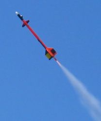
I saw a rocket that had active vertical stabilization (once.) It was at a TCC launch (near Fresno, Ca)
I don't remember the guy's name but I remember talking to him about how it worked.

As engineer, I really admired the (relative) simplicity of how it worked.

The rocket had 4 triangle shaped fins in the front of the rocket. It also had 4 photo cells that produced
a voltage proportional to the amount of light they are seeing. The system was set up to use the fact that
the sky is brighter than the earth. If a photo cell said it was dark, the system would assume that the ground
is in that direction, if it was light, it would assume that the sky was in that direction.

The really cool thing was that the system was completely analog. No computer. I'm not a control expert but ...
I think some sort of differencing was use to control the servos that moved each set of 2 fins on opposite sides
of the rocket. (It's been 3 or 4 years now. I'm sure the guy gave more information than that, but it's a bit hazy now. )

Not sure it that's helpful. I hope it's at least interesting.
 
What you're describing is sunguidance. I did that in 1988. Started with a more complicated sensing arrangement of phototransistors and comparator circuity. Before realizing I could simply use two photo-resistors, angled differently, with a voltage tap between them for an ultra-simple and more proportional response.

SunguidanceSensors.gif


So with an input voltage of 5.0V, pointing at the sun the voltage would be 2.5 volts and the servo for that axis would be adjusted straight. So when the sun was at a different angle to the photoresistor pair, the voltage would go above 2.5 or below 2.5 and cause the servo to move to steer the control fins for that axis accordingly (using a pretty simple servo circuit with voltage input, a 555 and 556 Timer IC for controlling two servos).

The avatar I use on TRF, is from video of a Sunguidance flight that was set for a very responsive ride.

Web page with more info is here: https://georgesrockets.com/GRP/RandD/Sunguidance.htm

BT-60 rocket weighing 14 ounces or less at liftoff

Sunguidance-P1010008.jpg


2005_03_12_381-crop.jpg
 
I know from my testing of the stabilization system electronics that roll is not good, and I know from my last test flight that control reversal is possible. So, I can either turn off roll control during the initial boost (until the first stage separates), or I can try to figure out how to design a free-spinning fin can. Let's try the spinning fin can idea for a bit and see what happens.

I haven't been able to find out much about how to design such a thing. So, I've come up with a trial-balloon idea and I could use some feedback. The attached pics show the concept. The foundation for the lower booster section is a standard fiberglass air frame. As it turns out, this would fit into the upper part of the booster air frame with no modifications. Perfect. The fiberglass air frame would extend about 1" below the bottom of the motor (a 98mm CTI N5800).

The spinning fin can would be formed from a tube rolled on the fiberglass air frame (the orange tube). It would therefore be a nice slip-fit over the fiberglass tube. The fin can tube would be supported on 4 or 6 or 8(?) yoke bearings. What is shown in the drawings are six, 1/2" OD bearings with #10 hardware axles. The drawing also shows a "green" coupler tube that would double the air frame thickness below the motor. The purpose of this would be to better support the bearing axles. However, it would be possible for this ring to be quite a bit thicker than coupler tubing if necessary.

To assemble this thing, you would insert the motor and attach it to the top of the fiberglass air frame (essentially a zipperless coupler). Then, you would slip on the fin can, insert the tube-doubling coupler, and then attach the bearings. This is pretty darn simple actually, so there must be a flaw. Thoughts?

Jim

Jim bit worried about the large area between the fin can and body causing too much friction. Have you considered allowing the interstage coupler to rotate instead?
 
Jim,

Two ideas. One, for the first stage, to replicate the "Spinnerons" as the Sidewinder missile uses. The other is..... add electronic roll control to the first stage booster, in between the fins.

Spinnerons look like a very interesting idea. I wonder if anyone has tried them before in a hobby context? Canards at the bottom of the booster aren't practical.

As for the cost of testing, this is why it would be so good if you had a much smaller model to do testing with.

Unfortunately, for the rear canard approach, it is difficult to come up with a smaller model. If you have a 4" air frame, then you need to boost a sustainer and the stabilization section to around Mach 1. It takes an N motor in the booster to do that. Testing forward canards is easier - J and K motors will work.

Fortunately, newbies at guidance having guidance realted accidents with big rockets, without learning on smaller ones first, has not become a problem, yet. I know of none so far. But it could be a problem eventually.

I was hoping to work out some of the bugs before generally releasing this approach. My beta group has been having successful flights and commercial units might become available. That might help to prevent problems, at least, that was the idea.

And IIRC you have a stage ignition lockout if it got way way off vertical before staging?).

Oh, yes.

Jim
 
OR....
One could add a twin flywheel roll control unit that is autonomous with respect to the yaw/pitch control.
Just leave the unit running at all times in the sustainer and let it correct for aerodynamic roll as well as control-surface roll coupling.

I'll get back to you on that one ....

Jim
 
Jim bit worried about the large area between the fin can and body causing too much friction. Have you considered allowing the interstage coupler to rotate instead?

Yep, that's the feature where I'm probably an idea short at the moment. The reason I think it would be OK is that I can create the rotating part of the fin can with exactly the tolerance that I want (since one part is made using the other part as the basis). It should also be possible to apply some lubricant between them (baby powder or something else). Finally, I don't think perfect freedom of the part would be needed. Any movement of the fins would tend to reduce the control reversal problem.

Movement of an air frame piece wouldn't solve the problem (or at least the problem I have). When the air frame is under thrust, the parts are locked together and can't turn. That would be most of the time period where I need to prevent the control reversal. I can imagine having a booster that pushes against an axial bearing such that it could turn under thrust. That would be quite easy to fabricate. The down side of that would be that much more mass would have to turn in response to a torque on the fins, but I think I will ponder that idea a bit more.

One thing that is in the back of my mind is that if the control reversal problem is common, then the stabilization approach can't be effectively used by others unless there is a relatively inexpensive way to prevent it. While it remains to be seen if it works, the concept I'm looking at would be at least be cheap and easy.

Jim
 
Maybe I'm way off on this one, but maybe let the sustainer spin the rocket, and then before the second stage ignites, "de-spin" with a yo-yo

No idea how you would do it, however you wouldn't have to change the sustainer at all or design a "spinning" fin can.

Explained in this video (skip to 4:00 for the yo-yo idea)
[video=youtube;-zJXRjG7DK0]https://www.youtube.com/watch?v=-zJXRjG7DK0"]https://www.youtube.com/watch?v=-zJXRjG7DK0[/video]
 
Jim - what about something like this? Fill a void between two rings with ball bearings. On my drawing it shows aluminum rings, but you could make these out of wood centering rings and cut the slots on a router table - I've done that before to centering rings. It doesn't need to be as robust as a car bearing - it will operate for 30 seconds, maybe?

Edward


SCAN0034.jpg
 
Jim - what about something like this? Fill a void between two rings with ball bearings. On my drawing it shows aluminum rings, but you could make these out of wood centering rings and cut the slots on a router table - I've done that before to centering rings. It doesn't need to be as robust as a car bearing - it will operate for 30 seconds, maybe?

Edward


View attachment 314126

I like that idea. Is there significance to the L-shaped rings? Why not just rectangular profile about the width of the ball bearings?

Jim
 
I like that idea. Is there significance to the L-shaped rings? Why not just rectangular profile about the width of the ball bearings?

Jim

Jim - that it to keep the ball bearings from falling out. They are captured between in that area.

Edward
 
So how about this approach? Bearings would be trapped between the motor thrust ring (CTI Pro98 Gen 2 ring) and "red" air frame tube, which is glued to the rotating fin can. Tubing at the top of the fin can would just overlap, but the surface areas of the parts that are in contact would be greatly reduced. One could remove the thrust ring to install the bearings and then screw it back on.

Jim

Spin plan 3.jpg
 
I think you also need bearings at the top - to keep everything centered and reduce friction. I just see the top binding a bit. In the graphic I added you can still assembly it by unscrewing the motor to tighten the system.

One thing that I didn't think about is how to keep the rocket above the motor from smooshing the bearings - I'm guessing it is accomplished through the green bulkhead and bolt?

Edward

spincan.png
 
Spinnerons look like a very interesting idea. I wonder if anyone has tried them before in a hobby context? Canards at the bottom of the booster aren't practical.

I saw another IREC team used steel disk rollers in spring loaded flaps on their fins. The rollers had little teeth that caught the airflow and spun up. In theory, when the rocket changed its vertical or roll orientation, the disks' rotational axis inertia would cause the flaps to deflect and create a restoring force (provided the rocket was flying straight to begin with of course).

Unfortunately, a recovery incident prevented a comparison flight against fixed fins.
 
I think you also need bearings at the top - to keep everything centered and reduce friction. I just see the top binding a bit. In the graphic I added you can still assembly it by unscrewing the motor to tighten the system.

One thing that I didn't think about is how to keep the rocket above the motor from smooshing the bearings - I'm guessing it is accomplished through the green bulkhead and bolt?

Edward

I would likely add the additional blue thrust ring to actually push on the air frame above. With the particular upper air frame I have (long story), it would work without the thrust ring, but that would be cheap insurance. The motor would push on the orange coupler and transfer force to the green bulkhead, the red air frame and the new blue thrust ring. As drawn, the only force on the bearings would be from the weight of the fin can.

I think upper bearings could be added. They would be radial only and not thrust bearings, which would be fine.

Jim

Spin plan 3.jpg
 
I've got plenty of powdered teflon if you need any - I can send you a 4oz bag.

Edward

Thanks! Let me make something and determine if lubrication is needed. If I can make what I drew, it won't be needed.

But keep those ideas coming. We're making progress!

Jim
 
So, if I roll the fin can tube using 0.005 mylar, I get a gap of 0.0775". Some 0.007 mylar would give a gap of 0.0795. The actual gaps might be just a bit larger. I can get 5/64" bearings (0.0781"). I think I just need to roll a couple of tubes and see which fits better.

I suppose I should allow for motor expansion, but for my use, this only needs to spin freely for about 5 seconds.

Jim
 

Attachments

  • Spin plan 3.jpg
    Spin plan 3.jpg
    28.5 KB · Views: 18
Of the two designs for the spinning fin can, I decided to try "Plan A" first, mainly because it should be easier to do. This design is shown in the first pic. I've made some progress and I think this design will work.

I started by rolling a 6-wrap tube that will be the base for the spinning fin can section (the second pic). The mandrel is the air frame tube. Eventually, I'll add fins and a tip to tip layup on this base.

The third pic shows progress on the bearing section. You can see the CTI motor and nozzle. The octagon-shaped piece is a 1" long coupler tube with epoxy used to form the octagon shape. The motor will be held just above this ring. The purpose of this piece is to provide more support to the bearing axles and also to provide a flat spot for the bearing axle hardware. I only have three bearings installed at this point (need to order the remainder). There will eventually be 7 or 8 - to be determined. You can also see the carbon spinning fin can section sitting on one of the bearings. To assemble this, you would slide the motor into the air frame, slide the fin can section over the air frame, insert the octagon-shaped ring, and then attach the bearings. Very simple.

Here's a vid of the spinning action. Note that the paper over the tube section is just to protect the peel ply finish from oils and dirt while I'm assembling things.

https://youtu.be/HqDxRWE1HY8

Jim

Spin plan 1.jpg

IMG_1121.jpg

IMG_1131.jpg
 
Their will be significant force on a very small area on the edge of the spinning can at the bearing interface, will the edge of a composite withstand that abuse? The shear on the individual fasteners holding the bearings will ultimately see the same force.

What is the friction interface between the ID of the rotating can and the OD of the interfacing tube? Will it withstand some major RPM. However, I doubt it will be a problem on one of your straight fin vehicles. ;)

P.S. My turning center is now functional if you need anything.

I don't have a complete set of data to work with yet, but roughly, I would expect the fin can to be on the order of 4 pounds. With a maximum acceleration of 12 G's, that gives 48 pounds of force. Roughly, the drag force should be on the same order (maximum velocity just a little over Mach 1), so roughly 100 pounds of total force on the bearings. It remains to be tested, but I don't think that will be a problem

The friction interface between the tubes is just the waxed air frame used for the mandrel and the waxed (at some point) ID of the fin can. There doesn't seem to be much friction at all.

Jim
 
It's the stress concentration at the fin tube / bearing interface that worries me. Wouldn't want to see the edge of the tube fail and prevent can rotation or worse total delamination of the can.
 
Spinnerons look like a very interesting idea. I wonder if anyone has tried them before in a hobby context?

Jim


Yes, I have done the Rollerons on BDCR at LDRS 20. I used a brass gear on ball bearings and high pressure air to spin them up just prior to ignition. They spun for minutes, well long enough for the flight so they did not need to be in the air stream to maintain the spinning motion. Here is an image prior to flight.

BDCR with Rollerons.jpg

They worked and at the same time didn't work. The did stop roll, but too well. The created too much torque and thus a washing machine effect oscillating the rocket back and forth, back and forth. The swing of the rollerons need to be dampened just the right amount for the given air speed to work correctly. I abandoned the idea and opted for a servo based system.
 
So, I have now tested both the Plan A and Plan B bearing approaches. Plan B is the approach in the first pic below (c/o AlphaHybrids). It uses a bunch of ball bearings between two air frame tubes. In the pic, I show the ball bearings between an air frame tube (on the top) and the motor thrust ring (on the bottom). However, the actual design has an air frame tube against the thrust ring, and the bearings are between the two air frame tubes. The lower air frame ring is attached to the motor and the upper air frame ring is attached to the spinning fin can section, and the bearings are between them.

I calculated a gap for the bearings of 0.0775". I got 5/64" bearings (0.0781") and also 1/16" bearings (0.0625"). Sure enough, the 5/64" bearings were just a bit too large and the fin can doesn't spin very well. However, the 1/16" bearings seem to be fine, and might allow for a little more motor expansion. There are 200 of them to fill the circumference.

The Plan A approach involves the 8 bearings under the spinning fin can. It's shown in the second pic.

The video shows both approaches.

https://youtu.be/wMZEbIaAlAw

Of the two, I suspect Plan B is better because the load is supported by a large number of bearings. Just need to keep dust out of the bearing area. On the other hand, 1/16" bearings are really small. If you play with them for a minute or so, you end up with a lot less of them than you started with. It's like they're gas molecules....

Jim

Spin plan 3.jpg
 

Attachments

  • Spin plan 1.jpg
    Spin plan 1.jpg
    48.5 KB · Views: 8
Post 1 of 4

Well, it's been three weeks since I last posted, but I've made a lot of progress on my free-spinning fin can. This would be for the first stage of my Balls three stager. I suspect there are folks that wonder if this is really necessary. I happen to think that it's quite necessary for the objectives of the flight (or I wouldn't be doing it), but it is resulting in a booster design that it pretty unusual. Here's a bunch of pics.

Since this booster will be part of the rocket for about 5 seconds, I'm just going to design it to do the assigned job and that's it. So, the fins will be 1/4" plywood laminated with 2 layers of vacuum-bagged carbon. The initial span of the fins in 9", but I will likely cut this down a little once I have all of the data needed to determine the rocket stability. I'm going to compress the layup between flat tiles, so I start out with a tile covered with parchment paper. After applying the carbon, I cover the carbon with peel ply and then one layer of breather (which is just enough breather thickness to soak up extra epoxy without pulling epoxy out of the carbon).

I learned here recently that the trick to getting a nice result with no fin warp is to laminate both sides of the fins at the same time, so I flip the layup and do the same process on the other side.

Jim

IMG_1179.jpg

IMG_1180.jpg

IMG_1181.jpg

IMG_1182.jpg

IMG_1183.jpg
 
Post 2 of 4

One thing I learned the last time I tried the tile method was that the pressure during vacuum bagging can crack the tiles. This time, I doubled up on the tiles to try and avoid this. I didn't have any problems. The 4-tile sandwich is shown in the pic.

The fins turned out quite well I think. After beveling the leading edges, I attached the fins to the carbon core tube, which I made previously. I always use a foam board template with angle iron to ensure that the fins are on straight.

Jim

IMG_1186.jpg

IMG_1187.jpg

IMG_1188.jpg

IMG_1191.jpg
 
Post 3 of 4

So, here's what this very strange booster looks like. It starts with the motor case, which has a section of air frame tubing that is held in place by the motor thrust ring. The fin can section has a similar air frame ring glued into it, and the ball bearings go between the faces of these two air frame sections. There is a second air frame section at the top of the fin can to help position that fin can around the motor case.

The bearings are loaded by turning the motor case/fin can section upside down. The paper just serves as a funnel to load the bearings. I ended up going with the 5/64" bearings, and I sanded out the bottom of the fin can section so that they would fit. Once the bearings are added, the assembly is turned right side up. The fin can spins quite well.

Jim

IMG_1192.jpg

IMG_1193.jpg

IMG_1194.jpg

IMG_1195.jpg

IMG_1196.jpg
 
Back
Top