Hybrids For 2015

The Rocketry Forum

Help Support The Rocketry Forum:

This site may earn a commission from merchant affiliate links, including eBay, Amazon, and others.
One caliber pre and 1.5 post is what It typically use. After 2 post you see diminishing returns AND you have to insulate that area well.

Edward

What would you recommend for a post-combustion chamber for a 54mm motor? Just a liner? Garolite tube? Graphite tube?
 
SCH 80 PVC is probably the easiest to fabricate and make. Typically I make my liners out of SCH80 PVC, so I just leave a blank space at the bottom of the grain for the post combustion chamber. For 54mm you should be able to use 1 1/2-inch SCH 80. Another important design element is to have a sharp transition from the grain to the post combustion chamber. This induces turbulence so things mix.

Edward
 
Any experience using a Bates multi-grain geometry to induce turbulence? The gap between the grains near the liner should be relatively cool and have a reducing atmosphere so the liner should not be hit too badly. Thoughts?

Gerald
 
I've never really worked with cartridge loaded hybrids. Almost always cast monolithic grains. Another fuel to try is 2-part urethane expanding foam. Add your goodies to one part of the mixture and the add the 2nd part. Pour rapidly into your casting tube and cap off. The advantages are that you can add just the amount of fuel you need and it expands to fill your casting tube. I've gone almost exclusively to this style of fuel.

Edward
 
I took a few pictures of the work in progress for THRP-1 (Tiny Hybrid Rocket Project 1) motor.

The coupler is nearing completion. The combustion chamber side is essentially machined though I may lighten it a bit more. The tank side does not have the holes yet for the bolt pins. The coupler also does not have the retention bolt holes for the injector assembly. The injector assembly slides in from the tank side of the coupler and butts up against the internal hard stop. It will have its own O-rings.

I left the O-rings off the tank side of the coupler. Each side has 3 O-rings. The two towards each end are gas check. The ones towards the middle of the coupler are for taking up slack and vibration absorption. I haven't done it yet but there will be a pinhole through the tank tube and combustion chamber tubes for pressure release just in case gasses get in there.

In the combustion chamber side of the coupler, the black tube stuck in the end is a section of 54mm phenolic liner being used as precombustion chamber thermal insulation. Retention is by the 4 bolts and washers on the end of the coupler. These should be considered sacrificial each burn as they will probably end up rather corroded.

I forgot to bring the nozzle over or I would have shown it. That part is done. It is a pretty conventional graphite nozzle; nothing special it's just shorter than average with a throat and convergent section machined better than most commercial nozzles. Note to those who don't know - a long throat in a nozzle costs perhaps 10% total ISP. Most commercial nozzles have long throats...

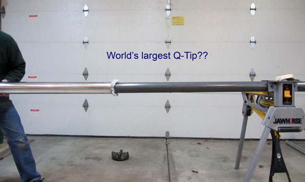
I didn't bring the tank tube. Right now it is just a squared off length of 6061-T6 DOM seamless tubing. It's perhaps 2 1/2 times the length of the combustion chamber. For scale, the motor is 76mm and somewhere around 5' long, and will be an M.

I'll provide more pictures later when I have something more to show. Since I'm manually machining everything and often with what is not really the appropriate tools, it goes a little slowly. It doesn't help that the bolts I have are a little long and need to be ground down - there are a lot of them!

Yes there are more bolt pins than really needed, particularly because this is a low pressure hybrid design via valve regulated tank pressure. But the design is for a minimum diameter rocket. The motor is the body. The coupler therefore needs maximum stability. Clearance on insertion is about 0.0015" and the O-rings are under some compression - a bit more than usual usage. The multitude of pins provide some additional stability. Besides, changing out the injector assembly, the nozzle, and the upper bulkhead with its valve allows me to choose different operationg pressures and mass flow so there is a lot of flexability for burn profiles. If I up the operating flight tank pressure (which drops ISP for N2O hybrids) then the pins are a little more appropriate in count.

My plan was to complete the motor this week but that might not happen. The horizontal bandsaw decided to quit working halfway thruogh a 3" aluminum bar which was going to be the upper bulkhead. Rather than fix the bandsaw at the moment, I ordered some more metal already cut to length. But it might not be here this week.

Incomplete coupler and combustion chamber.jpg

Incomplete tank side of coupler.jpg

Essentially complete combustion chamber side of coupler.jpg

Gerald
 
Last edited:
Looks very nice! Is there a reason you went with separate pieces of aluminum for the tank/combustion chamber versus a floating bulkhead design with a long piece of tubing? The 3" N motor that I have uses an 84" piece of tubing and the injector/fuel grain/nozzle go in from one side and the other end get the forward closure/coupler.

Edward

Getting and transporting a long enough piece of aluminum, plus being able to machine it. These smaller pieces I can fit on my Bridgeport without the tubing hitting the walls. Longer though... I could have machined the holes for the pins for the bulkhead but would have difficulty with machining around the ends of the tube. A monotube arrangement even with a pinned injector assembly would have required much less machining overall and would have come out approximately one pound lighter. I didn't want a floating injector as I don't like the idea of subjecting the fuel grain liner to those pressures - somewhat over 3000 pounds with this design in the higher ISP version and higher for the higher impulse version.

The lathe I have access to cannot machine the current tank tube as it is too long. I had to get that already squared on the ends. The tube is within one or two inches of the longest that person's lathe can deal with. They might be out of the business now even - it was the person who machined for Gorilla; nice gentleman to work with.

I would rather have used one long tube. That's essentially how I designed it. But I couldn't make it that way.

Gerald
 
I went on a mission to reduce weight in the coupler. This has added hours to the machine time. I'm not done yet, but will be mostly done this weekend. Odds are I will not get to machining the injector assembly but it is a comparatively minor job. Also the fuel grain won't have been cast. But first opportunity to my knowledge for a static test is about 6 weeks away. I'll need to get GSE help to even make that test.

I needed to do a bit of remachining as tolerances were a little too tight. Disassembly of the motor was a two person job with the aid of a bench vice. I don't think one person could have disassembled it. So I took perhaps another thousandth off the coupler OD which should help. However I haven't reassembled to test the fit. I'm also hoping my skeletonizing the coupler will reduce the required force for disassembly.

For those who have done so, what do you recommend as the best way to clean the inside of the tank tube to make it safer for nitrous? Is the routine of acetone, denatured alcohol, increasing grades of H2O2, required, as it would be if the oxidizer were O2 or H2O2? Or is a good cleaning with acetone and possibly alcohol and a good drying sufficient? I know not to leave any organics behind.

I'll get some more pictures in the next few days. I have gone a bit crazy on that coupler! It has shed 150g and more will come off by the time it's done.

It's looking like I'd have to go to Argonia or Black Rock to fly this one as a minimum diameter if it performs like it is supposed to (north of 20K and south of 30K). Then logistics become a pain for the GSE, plus it is hard for me to get the time to make such a trip. Potter lost waiver but I might be able to pile enough mass on to compensate. Sticking THRP-1 inside a bigger tube is more likely to happen as then it could be flown locally at Battle Park or MDRA. I don't think any site this side of Argonia has a waiver of 20K or more now.

Of course, assuming the motor actually works...

Gerald

Why not just test fly it with a lower N2O fill? Put a closed tube in the tank to reduce the volume.
 
Coupler, essentially completed... There are holes still remaining to be made for the pins that will keep the injector assembly from moving around before the tank is pressurized. They are a convenience feature; those pins are not structural. But otherwise this coupler is finally done and fits both the tank and the CC.

Obviously I made some effort at reducing waste mass. I managed to remove approximately 170g. It now weighs a little under 1.6# without the pins or the precombustion chamber liner or O-rings. I could have removed more, but, this is good enough.

The metal I need for the upper bulkhead arrived yesterday - requiring signature. I hate it when that happens for a cheap order. So tonight I got the metal. Likely tomorrow I'll be machining it.

After that comes the injector assembly and casting a fuel grain. I also keep forgetting to order the correct O-rings for the tank.

Gerald

Coupler nearly completed.jpg
 
Flew my first ever hybrids yesterday can't wait to fly more next month.

ImageUploadedByRocketry Forum1442190877.612454.jpg

ImageUploadedByRocketry Forum1442190771.242182.jpg
 
Flew my first ever hybrids yesterday can't wait to fly more next month.

View attachment 271924

View attachment 271923

The pics are great, but um... you seem to be missing some key information here:

What brand and size; what motor designation etc etc... out with it man!

The pics look great, love the shot of the red rocket... seems kind of short for a hybrid, have any more details?
 
Last edited:
The red rocket was a wildman punisher on its maiden flight had a 38mm skyripper 38/220 with a polypropylene fuel grain . Went a whopping 714ft! I was prepping for the next case up in the skyripper line the I motor but we were shut down due to rain

The green rocket it is an Estes partizon flying on a 29mm skyripper abs fuel grain that was the first flight of the day It went 1162 ft.
 
Love the SkyRipper product line... it is a shame that they are no longer able to sustain a business for us end users. Beautiful pics, thanks for the details!
 
For those who have done so, what do you recommend as the best way to clean the inside of the tank tube to make it safer for nitrous? Is the routine of acetone, denatured alcohol, increasing grades of H2O2, required, as it would be if the oxidizer were O2 or H2O2? Or is a good cleaning with acetone and possibly alcohol and a good drying sufficient? I know not to leave any organics behind.

Gerald


Hi Gerard,

Nice looking hardware, although it seems awfully complex.

I just use Acetone and don't worry after that. The cloth is soaked in Acetone.

--MCS

qtip.jpg


.
 
I like that approach. I was thinking about wrapping a rag around a cleaning brush but a tube like you've done looks easier to deal with. Plus the brush is never clean as it's been used too much. Thanks for the idea!

Gerald
 
Coupler, essentially completed... There are holes still remaining to be made for the pins that will keep the injector assembly from moving around before the tank is pressurized. They are a convenience feature; those pins are not structural. But otherwise this coupler is finally done and fits both the tank and the CC.

Obviously I made some effort at reducing waste mass. I managed to remove approximately 170g. It now weighs a little under 1.6# without the pins or the precombustion chamber liner or O-rings. I could have removed more, but, this is good enough.

The metal I need for the upper bulkhead arrived yesterday - requiring signature. I hate it when that happens for a cheap order. So tonight I got the metal. Likely tomorrow I'll be machining it.

After that comes the injector assembly and casting a fuel grain. I also keep forgetting to order the correct O-rings for the tank.

Gerald

You made that on an Atlas? You're either crazy or MacGyver!
 
Where did you find your polyethylene powder? Mostly what I've seen is either quite high prices or quite large quantities.

Gerald

The brand is Plascoat NG30. It is black and I have noticed an ISP jump when compared to PVC.

Edward
 
Thanks for the info Edward. I'll have to check it out.

I had a minor machining setback tonight. I need to remake the upper bulkhead. I was tapping for the valve (1/4 NTP) and when I went to back the tap out, it snapped. It was a new tap too... Oh well. Wasted day's work.

Gerald
 
Thanks for the info Edward. I'll have to check it out.

I had a minor machining setback tonight. I need to remake the upper bulkhead. I was tapping for the valve (1/4 NTP) and when I went to back the tap out, it snapped. It was a new tap too... Oh well. Wasted day's work.

Gerald

That is never fun, I feel your pain. I had a professor in college that I had shop class with and he gave me these tips for tapping. 1) Use Crisco or Lard for lubricant. 2) For NPT taps, buy (and use) the tap reamer for the size. 3) For NPT, use interrupted thread taps. 4) Spiral flute taps when possible.

Edward
 
And flight weight throttable hybrid hardware. This one will use an MD sized cylinder for around 9,000Ns. The ME version will be around 15,000 Ns. Same combustion chamber for both. The MD is mainly for development and refining of the control system in flight.

Edward
 
Bob - we need to get you a Jump to Conclusions Mat. This is not complete. I still have to tap the side of the adapter for 1/16 NPT as well as 3/8-24 for a 1800 PSI burst disk (same as used on CO2 tanks). The plug valve on this actually has a channel cut in it on the downstream side that will drain the orifice when the valve is closed. There is only an o-ring seal on the upstream side.

Edward
 
Why not just test fly it with a lower N2O fill? Put a closed tube in the tank to reduce the volume.

You know, I'm not sure of a good way to do that. Fill is from the bottom side, through the injectors; valve is on the top. Hybrids have a lot of shake and rattle as the combustion is not as stable as a solid can be - due to low particulate so low acoustic dampening plus pressure feedback through the injectors. I'd have to make centering accomodation at each end of the tube and make it full length to keep it from moving. It would also have to be absolutely leak-proof or it would be a safety issue. Perhaps I'm missing something but it seems to be a bit of work to make that work well. Perhaps I'm misunderstanding what you have in mind.

-----

I got in about 5 hours machining today so I'm nearly back to where I was on the upper bulkhead. Hopefully there won't be any more setbacks.

Gerald
 
You know, I'm not sure of a good way to do that. Fill is from the bottom side, through the injectors; valve is on the top. Hybrids have a lot of shake and rattle as the combustion is not as stable as a solid can be - due to low particulate so low acoustic dampening plus pressure feedback through the injectors. I'd have to make centering accomodation at each end of the tube and make it full length to keep it from moving. It would also have to be absolutely leak-proof or it would be a safety issue. Perhaps I'm missing something but it seems to be a bit of work to make that work well. Perhaps I'm misunderstanding what you have in mind.


Gerald

A plastic liner that slides in and reduced the ID of the tank. Want me to print one for you?

--john
 
John,

Thank you for the offer, but no. Many plastics are not compatible with N2O. N2O is a mild solvent for some plastics and rubber compounds, and is sensitized by them. But it is an interesting approach. You wouldn't be able to print it anyway, not in one piece. It would be too long at around 3' or so.

Gerald
 
Machined a new adapter. The other one was the first one and generally those go to the recycle bin because I realize that I can optimize it. This one is 1/4" shorter, the tap depth for the valve is more appropriate and I lengthened the threaded section on the external threads. I also added a burst disc to this. I still haven't decided on how to do the pressure tap yet. I've done 1/16 NPT on the test stand hardware but I need to assemble everything to see where there will be some room to put the transducer. My next step is to add about a pound of CO2 to the tank and pressure test for leaks and run the servo through the paces.

IMG_0064.jpg

Edward
 
Back
Top