Two Stage AP Motor????

The Rocketry Forum

Help Support The Rocketry Forum:

This site may earn a commission from merchant affiliate links, including eBay, Amazon, and others.
30 posts and not 1 picture???

JD

I don’t own a camera. I’ve owned three digital cameras over an eight year period of time and they all crapped out on me.

I’m not willing to drop $200 or more for another one that will probably last less than three years.
 
I don’t own a camera. I’ve owned three digital cameras over an eight year period of time and they all crapped out on me.

I’m not willing to drop $200 or more for another one that will probably last less than three years.

Phone?
 
Does anybody have a Rock Sim file for this kit?

I’d kind of like to know the CP; preferably in both its single and two stage configurations.
 
Assembly wise the rocket is completed and could be launched tomorrow; though I’d really prefer to get at least a coat of primer on before exposing it to the elements.

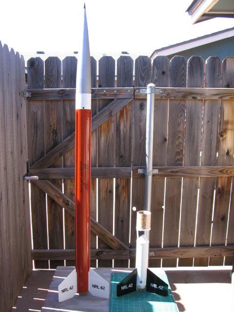
A friend had a set of RockSim files on his computer and it is apparent that the CGs are going to be way, way ahead of the listed CPs. And yes I am using the pleural as there are two each, one in its two stage configuration and one as a single stage.

Funny thing; the CP as a two stage rocket is located below the upper stage’s airframe and is a point in open air.

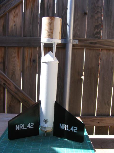
The over stable, (multiple caliber?) aspect of this rocket coupled with its ginourmous fins, you got to see them to believe them, leads me to believe the rocket will be prone to weather cocking badly.

Has anybody ever had to add weight to the BACK of a rocket to insure better flight characteristics?

Above all else I’ll be attending a P.A.R.C. meeting/launch this coming weekend, weather permitting and the river doesn’t rise, which should give me the chance to get some pictures taken and perhaps posted.
 
Just use a fairly high thrusting booster motor, and you'll be fine. I haven't launched mine in 2 stage configuration yet (too chicken), but I've launched the upper stage alone on a fairly windy day, and it did fine.
 
I have some Loki G80s coming my way along with the appropriate case and nozzle that I’ll use in the booster; probably with an AeroTech G64 in the sustainer.
That should be good for a first PoC launch before I transition to more formidable motors.

This weekend’s P.A.R.C. launch has been cancelled due to weather but there will still be a meeting so I should get some pictures taken I can post.
 
Well obviously the pictures were never taken. By this point the rocket is completed and painted with only the decals needing to be applied.

First chance to launch will be early April at Argonia so I still have a bunch of time to sort out the small stuff.

I was planning to use a Loki G80 in the booster for the first flight but after talking to Pete he mentioned that drilling the delay grain down to only 4 seconds is a “bad thing” as that makes it so thin at the top it could blow through causing a premature deployment of the chute.

The Rocsim files I’ve seen are a bit confusing as they say to use an AeroTech G80 with a 1.64 second delay. As the AeroTech G80 is a single use motor you can’t drill/cut the delay this makes no sense.

Definitely going to be talking to some of the good folks at KloudBusters before its inaugural flight.
Have arrived at a name for this rocket “It Works In Theory”.
 
The kit was originally developed when the AeroTech G80-4 was in production. I have not flown this kit in years, but I believe that the G76-7 drilled down to -4 should be a good option. Again, I have yet to test this.
 
001_zpsucwkbaqx.jpg

Here is the completed Cosmodrome “Aerobee Hi” in all its Orange Glory.

002_zpsicxbh3yh.jpg

Close-up of the booster.

003_zpsgwsyifgu.jpg

This is where the altimeter will be installed. It will be used to deploy the sustainer’s chute at apogee.
I chose to use altimeter deployment vs motor deployment for two reasons. 1: It will still deploy a chute even if the sustainer motor fails to ignite. 2: I didn’t have to build in a bunch of ductwork around the lower electronics bay to allow for motor deployment.

004_zpsimgbyaln.jpg

And here is the lower electronics bay where the timer and battery will be located that are used to fire the sustainer motor.
That entire e-bay is built inside a BT-80 coupler and can be removed by unbolting it from the upper motor tube centering ring and pulling it out the top.
The hatch allows me to install/remove either the battery alone or the complete timer, though the latter is a pain.
 
006_zpstbh0e8dw.jpg

The booster uses simple motor deployment.
I built the booster with a 38mm motor tube as opposed to the provided 29mm as I wanted to be able to use Loki G80s and perhaps an Aerotech H123.
 
Back
Top