# of Layers of Carbon for L3?

The Rocketry Forum

Help Support The Rocketry Forum:

This site may earn a commission from merchant affiliate links, including eBay, Amazon, and others.

sailmike

Well-Known Member
Joined
Jan 19, 2009
Messages
498
Reaction score
3
I've lately been toying with the idea of building a rocket capable of level 3 flight, but still light enough to take most 38 mm motors. I'd like to be able to fly on a 75 mm M1850. My tentative design is almost 7' tall and 4.5" in diameter. Thing is I don't know how many layers of 5.6 oz carbon is the minimum to handle that motor. I've also thought about going with John Cokers idea of using honeycomb to make the body tubes.

Another thing I've been thinking about is the centering rings. They hold the motor to the body tube, but do so perpendicularly to the body tube. That is the worst angle to brace the motor. So, with that in mind, the centering rings wouldn't have to be very thick and three rectangular pieces could be glued to the forward side of the rings and from body tube to motor tube.

My design calls for a conical nosecone, because I would have to fabricate my own and that would the easiest to make. Can't seem to upload my file, it's too big.

So, how many layers is the minimum at 4.5" diameter to handle a M1850?

Thanks a lot,
Mike
 
Oh yeah, forgot to add that the centering rings, bulkheads, and fins would all be made from a carbon and balsa sandwich, probably three 1/8" sheets of balsa for the bulkheads and two sheets for the centering rings and fins.

Thanks a lot,
Mike
 
Mike,
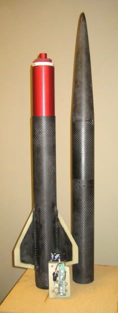
This won't answer your questions but will give you some idea. I have a 3" min dia rocket that I layed up using 5 layers of 5.7 oz carbon fiber. It's plenty strong for 3" motors. I hope to fly it at XPRS on the AT M1450

XPRS2.jpg


I've layed up some 98mm tube using 5 layers of 6 oz (.014) The tube wall is .080 and is plenty strong for anything you could put in it.

98.jpg


Tony
 
Do you plan on adding some nose weight? When I downloaded your rocksim file on my computer and loaded it with the M1850 it showed as unstable.:dontknow:

Perhaps bigger fins?

Cool project. You should also check out Performance rocketry. They have 4.5 inch tubes and nose cones; might be simpler to buy a nose cone from them than make one.

Just a thought.
 
Well that many layers would make my rocket a bit too heavy for most of the 38 mm motors. I'm thinking that your rocket is thinner and, therefore, has less overall drag. Less drag means less force on the airframe and so you wouldn't actually need that many layers? My design has a larger diameter airframe, so it will have a lot more frontal drag. Still, I'm seriously thinking of going with the honeycomb design as demonstrated by John Coker on his website.

https://www.jcrocket.com/honeycomb.shtml

Mike
 
Afterburner, the Rocksim file I uploaded here is without the parachute, shockcord, and other items. I deleted them to help get my file size down. After deleting all the simulations, the program still said it was too big for some reason. I do plan on adding more weight to make it more stable.

2.37 layers, huh. I was thinking that 2.374691 layers might be adequate.

Mike
 
Well that many layers would make my rocket a bit too heavy for most of the 38 mm motors. I'm thinking that your rocket is thinner and, therefore, has less overall drag. Less drag means less force on the airframe and so you wouldn't actually need that many layers? My design has a larger diameter airframe, so it will have a lot more frontal drag. Still, I'm seriously thinking of going with the honeycomb design as demonstrated by John Coker on his website.

https://www.jcrocket.com/honeycomb.shtml

Mike
Mike

Newton's law requires that for every action there is an equal and opposite reaction.

The instantaneous motor thrust is the load on the rocket which has nothing to do with the frontal area or drag. The peak thrust of an AT1850 is 550 pounds at lift-off where there is virtually no aerodynamic load. You airframe must be stiff enough so it will not buckle (column buckling failure mode) and you fins must be stiff enough so the will not flutter and fail at max V.

A CF airframe wall thickness of 1/16" to 3/32" should be stiff enough to prevent buckling and a CF fin thickness between 1/8"-3/16" should be stiff enough to prevent flutter.

A 4.5" diameter CF AF with 1/16" walls will weigh about 250 grams (or about 9 oz.) per lineal foot. A 1/8" thick CF plate will weigh about 3 grams per sq. in. (or about 1 pound per sq. ft.). Increase these weights by 50% if you use the thicker values.

Bob
 
Thanks guys for your replies! My design's walls are a little more than 1/16" at the moment, but this value I have is without epoxy, which will make it quite a bit more than 1/16 when done I would think.

Three wraps of 5.6 oz carbon will get get me more than 1/16" and this is without the epoxy. I'm thinking of making the nose weight removable. One weight for the biggest 38 mm motor, another weight for the biggest 54 mm motor, and one more weight for the biggest 75 mm motor. You guys have any creative ways of adding removable nose weight? I'm sure there are a lot of creative ways of doing that. I'm thinking of putting some all thread and making a bulkhead that fits close to the tip of the nose but leaves enough room to add weight behind it. Another bulkhead would go closer to the base of the nose cone for the shockcord attachment.

Thanks,
Mike
 
Mike

Newton's law requires that for every action there is an equal and opposite reaction.

The instantaneous motor thrust is the load on the rocket which has nothing to do with the frontal area or drag. The peak thrust of an AT1850 is 550 pounds at lift-off where there is virtually no aerodynamic load. You airframe must be stiff enough so it will not buckle (column buckling failure mode) and you fins must be stiff enough so the will not flutter and fail at max V.

A CF airframe wall thickness of 1/16" to 3/32" should be stiff enough to prevent buckling and a CF fin thickness between 1/8"-3/16" should be stiff enough to prevent flutter.

A 4.5" diameter CF AF with 1/16" walls will weigh about 250 grams (or about 9 oz.) per lineal foot. A 1/8" thick CF plate will weigh about 3 grams per sq. in. (or about 1 pound per sq. ft.). Increase these weights by 50% if you use the thicker values.

Bob

Well, the peak load could be significantly less than this for a regressive motor in a minimum diameter lightweight rocket. If the motor is a significant fraction of the mass of the rocket, the rocket will only feel a portion of the thrust, with the rest of the thrust going to the acceleration of the motor itself. The airframe would feel a force proportional to F=MA, as would the motor itself, but if the motor is a significant portion of the weight, the motor portion becomes significant.
 
Like Bob said, the failure mode that you are most likely to experience is buckling.

The critical loading function for a column is:

F = pi^2 E I / L^2

E = Young's modulus (aka stiffness)
I = second moment (geometric property)
L = effective length (just length of loading section in free-free)
F = critical loading force (exceed it an failure occurs)

Derivation of this formula comes from the special case solution sets of Newtonian motion in elastic bodies.


Suppose you wish to design for 2500N, with an ID of .114 m (4.5"), perhaps 2 m long, and safety factor of 2.

The second moment (I) for a tube is:
I=pi/4 (Ro^4-Ri^4) = pi/4 (Ro^4-.057^4)

The young's modulus (E) for CF composite is roughly:
E=75 GPa

2500 * 2 = [pi^2 * 75*10^9 * pi/4 (Ro^4 - .057^4)] / 2^2

Ro=0.0571

Yeah, that is 0.1 mm wall thickness... now I'm not so sure you're rocket is going to fail due to buckling. I guess I'm just used to really thin rockets...

Consider failure due to compression...

2500 = pi * (Ro^2 - Ri^2) * sigma

sigma = acceptable stress level... let's say 200 MPa for CFRP
If you do the calc you find another incredibly small wall thickness (or perhaps my solver is just messed up?)

But this is assuming no asymmetric loading on the rocket. Analysis for that can be done by doing beam modeling and finding where the normal stress exceeds the material limit.

Anyways, I think you get the idea. Sorry I couldn't get numbers for you...wish I had a calculator.
 
Well, the peak load could be significantly less than this for a regressive motor in a minimum diameter lightweight rocket. If the motor is a significant fraction of the mass of the rocket, the rocket will only feel a portion of the thrust, with the rest of the thrust going to the acceleration of the motor itself. The airframe would feel a force proportional to F=MA, as would the motor itself, but if the motor is a significant portion of the weight, the motor portion becomes significant.
Not true. The load is carried thoughout each cross-section of the rocket. The weakest point is the potential failure point. An example is shown below.

IMG_2041.jpg


Cesaroni 634I540-16WT, 21oz engine + 42" long, 12oz mach buster rocket = 1000+ MPH shred. The failure mode was column buckling of the airframe just above the motor casing. The actual breakup was caught on video and the key frames are shown below.

2007-06-mach-busted-series.jpg


The Cesaroni I540 engine generates an average of 121 lbs of thrust for 1.17 sec. These images taken from 30 frame per second video, image and shred times determined by counting frames. Speed vs. time estimated by RockSim. Breaks mach in 0.5 seconds at 270 ft. altitude while pushing 75Gs. At 0.7 sec front of rocket disintegrates releasing a large amount of red chaulk dust. Back half of rocket, with engine and fins continue under power for almost 0.5 sec more.

Bob
 
Like Bob said, the failure mode that you are most likely to experience is buckling.

The critical loading function for a column is:

F = pi^2 E I / L^2

E = Young's modulus (aka stiffness)
I = second moment (geometric property)
L = effective length (just length of loading section in free-free)
F = critical loading force (exceed it an failure occurs)

Derivation of this formula comes from the special case solution sets of Newtonian motion in elastic bodies.


Suppose you wish to design for 2500N, with an ID of .114 m (4.5"), perhaps 2 m long, and safety factor of 2.

The second moment (I) for a tube is:
I=pi/4 (Ro^4-Ri^4) = pi/4 (Ro^4-.057^4)

The young's modulus (E) for CF composite is roughly:
E=75 GPa

2500 * 2 = [pi^2 * 75*10^9 * pi/4 (Ro^4 - .057^4)] / 2^2

Ro=0.0571

Yeah, that is 0.1 mm wall thickness... now I'm not so sure you're rocket is going to fail due to buckling. I guess I'm just used to really thin rockets...

Consider failure due to compression...

2500 = pi * (Ro^2 - Ri^2) * sigma

sigma = acceptable stress level... let's say 200 MPa for CFRP
If you do the calc you find another incredibly small wall thickness (or perhaps my solver is just messed up?)

But this is assuming no asymmetric loading on the rocket. Analysis for that can be done by doing beam modeling and finding where the normal stress exceeds the material limit.

Anyways, I think you get the idea. Sorry I couldn't get numbers for you...wish I had a calculator.
I think you forgot that CRFP is brittle and fails at 1-2% of Young's Modulus values. Simple buckling approximations do not assymtote until L/D > 8.

Below are some papers you might find useful.

https://www.esm.psu.edu/courses/emch213d/tutorials/design_notes/docs/design_buckling/bucdes1u.pdf

https://www.civil.northwestern.edu/people/bazant/PDFs/Papers/422.pdf

Bob
 
Very cool photo sequence, Bob and thanks for the links to the papers. Buckling is a real issue and I agree that's what caused Boris's rocket to break up.

But CJL is right. The load on the airframe at liftoff is not the total thrust of the motor, but rather the acceleration of the rocket * the non-motor mass. Otherwise, the motor would stay on the pad and the airframe would take off with a much higher acceleration than actually happens. ;)

With Boris's rocket, clearly the rocket didn't fail at liftoff, but significantly later in the flight. This is a great example of how the airframe load can go up later in the flight due to a combination of aerodynamic load and acceleration loads. Toward the end of the burn, more of the motor thrust is going to punching through the air (which applies load to the airframe), and less of it is going to accelerating the mass of the unburned propellant (which doesn't). The motor burn doesn't even have to be regressive, because as the rocket speed goes up, the drag forces go way up, enough to be quite significant. With this sort of Mach-busting flight, it's not uncommon to see the rocket decelerate at 20 Gs at burnout.

When performing the buckling calculations, the axial load on the airframe should be checked both at maximum motor thrust (typically at liftoff) and just before burnout. The total airframe load will be the sum of the nosecone drag, the airframe drag, and the acceleration * the non-motor rocket mass. You can use Rocksim's Cd analysis to see the ratio of the (nosecone + airframe) to the total drag, and apply that fraction to the total aerodynamic drag that Rocksim computes.
 
The following conservation equation is valiid throughout the flight.

F thrust = ma - mg + 0.5 Cd A Rho V^2 = m (g-1) + 0.5 Cd A Rho V^2 where a is expressed in G.

The thrust of the motor is the action force, and the inertial and aerodynamic drag are the reaction forces. The inertial force pushes up the airframe and the aerodynamic forces push down on the airframe so the load on any crossection of the airframe is a constant. At launch the inertial reaction to the thrust of the motor is the dominant force, at max V the aerodynamic reaction equals the inertial reaction so the forces are equal, and at burnout the aerodynamic reaction is the primary force.

Bob
 
F thrust = ma - mg + 0.5 Cd A Rho V^2 = m (g-1) + 0.5 Cd A Rho V^2 where a is expressed in G.
Almost. On the right side of the equation I think there's a typo and a sign error and you meant to say:

F thrust = m(a + 1) + .5 Cd A Rho V^2

The point that cjl and I were making is that the m(a+1) can be decomposed into (m_motor + m_airframe)(a+1), where only the m_airframe part of it puts axial forces onto the airframe tube. For that matter, the load on the tube is not constant through length of the rocket, unless the nosecone is the only part with any mass. Instead, the stresses on the tube are highest at the motor thrust ring, and are reduced as you move up the rocket. The forward end of the airframe tube only has to push on the nosecone with F = m_nosecone(a+1) + drag_nosecone. This is why you see Boris's rocket failed at the lowest point of the rocket that was free to buckle (the motor casing prevented catastrophic buckling in the rest of the tube)

As long as we're doing real engineering, does anyone have equations or rules of thumb for the bending moments experienced by a rocket in flight? For a long, skinny rocket, I would expect that a bending torque could add a lot of stress on the compressive side of the bend. The safe thickness calculated by the critical buckling load equations may need to be significantly increased to account for this.
 
"So, how many layers is the minimum at 4.5" diameter to handle a M1850?"


While I admire and envy those that can work with CF, my answer is simple.

Zero layers of CF are required for a M1850 L-3 bird. That's how much CF was on my L-3 bird and it worked fine (I did glass the airframe).

There is a guy here on the forum that flew a stock LOC Airframe with an "M". Thats right, nothing but cardboard and it performed well.

To each his own.
 
Mike, my L3 rocket survived an N-4000 and several other N motors. The diameter is 4.1 inches (slightly oversized), and it was constructed out of 5 wraps of 5.7 oz carbon with a wall thickness of about 0.055". Total weight without motor is 16 lb. I can't view your rocsim file, so I don't know how your design compares. However, I would guess that my design would work on an average M with 4 wraps but probably not 3.

In the most recent version of this rocket, I used 5 wraps again, but was able to shave weight elsewhere, mainly around the electroncs bay.

HCY #1.jpg
 
There is a guy here on the forum that flew a stock LOC Airframe with an "M". Thats right, nothing but cardboard and it performed well.

To each his own.
Dave,

Are you advocating that someone NOT overbuild their rocket? How outrageous! That's blasphemy. You'll be hanged, drawn and quartered, and burned at the stake, all at the same time :D

Doug


.
 
Very cool photo sequence, Bob and thanks for the links to the papers. Buckling is a real issue and I agree that's what caused Boris's rocket to break up.
.

Buckling of what though Adrain?

I've flown LOC 38mm kraft tube that Boris' rocket was made from on an I540 to 1010mph and recovered fine. all cardboard except an ACME fin can.

Later that year I flew it on a J570 at black rock, and the up part was again A-OK. The down part had failure to light e-matchs however.

The differance is I used an 8" coupler that was reinforced with two slit couplers so I would not get a fold at the coupler joint like I did in my larger 2.56" rocket the year before.

Could Boris' rocket first have failed at the coupler joint like many Mach failures do and then rip the rest apart ?

Pic of 38mm LOC Cardboard rocket on J570 below, airframe all intact till impact with playa

playadart_sm.jpg


Video of several rockets failing at the coupler joint, one LOC tube 2.56", one CF 54mm and one 4" fiberglass

A wind shear was thought to have created the extra stress on the coupler joints.

All three rockets failed at the same ~7000 AGL altitude based on recovery of the flight data from ARTS flight computers

The 2.56 rocket was at 1121mph, the 54mm was at 1228mph, and the 98mm rocket was at 1318mph

https://boostervision.com/wmv/bvbrtrailer.wmv
 
Could Boris' rocket first have failed at the coupler joint like many Mach failures do and then rip the rest apart ?

Could be. From the post-flight pictures it's not clear to me that he actually had a coupler, and the wrinkling of the tube at the top of the bottom section looks like it's consistent with column buckling. But if there was a coupler and it buckled there first, then I can imagine how the resulting aero torques could cause the damage we see at the top of the motor tube. But I could only guess without more information about the details of the structure.

When I get home I'll check out the video. Should be interesting.
 
Dave,

Are you advocating that someone NOT overbuild their rocket? How outrageous! That's blasphemy. You'll be hanged, drawn and quartered, and burned at the stake, all at the same time :D

Doug


.

Well .... kind of. I think all L-3 Rockets are overbuilt. It seems to be the way to go. I know I overbuilt mine, but not too bad. Hey 6" OD and 11-5 feet long, weighed 42 lbs on the pad. Thats not that bad ....

I actually wanted the weight, I tried to keep it at a reasonable altitude. It went to about 7K, a little higher than I wanted. The bad part wasn't the trip up, it was the trip down where I met Mr Murphy. He directed the rocket to the top of the largest Pecan tree I have ever seen.

What a mess.
 
There was no coupler in the pictured LOC Weasel. Went with a solid tube and engine deployment to maximize simplicity and minimize weight and failure points. West 206 epoxy and 2oz FG tip to tip kept the surface mounted fins on OK, no FG above the fins.

Did not expect to get the rocket back unless we got lucky.

Flight video: (don't blink) https://bpasa.com/bpasa/Movies/X16.wmv

Picture below is my engineering consultant. His analysis of the rocket design is written on his shirt :cool:

Will fly it again this year at NERRF 4 with a light wrap of FG on the new body. Same awesome CTI I-540 engine.

IMG_1552s.jpg
 
Mike, my L3 rocket survived an N-4000 and several other N motors. The diameter is 4.1 inches (slightly oversized), and it was constructed out of 5 wraps of 5.7 oz carbon with a wall thickness of about 0.055". Total weight without motor is 16 lb. I can't view your rocsim file, so I don't know how your design compares. However, I would guess that my design would work on an average M with 4 wraps but probably not 3.

In the most recent version of this rocket, I used 5 wraps again, but was able to shave weight elsewhere, mainly around the electroncs bay.

Now heres a guy that knows what hes talking about.

Jim,
See you in Amarillo!
 
There was no coupler in the pictured LOC Weasel. Went with a solid tube and engine deployment to maximize simplicity and minimize weight and failure points. West 206 epoxy and 2oz FG tip to tip kept the surface mounted fins on OK, no FG above the fins.

Thanks for the info Boris,

then I wonder why your tube failed and the others I have flown and seen flown by others have not failed?

Did you have a vent hole in the rocket?

Could the nose cone have been poped off in flight and the tube section from the nose cone down zipped by the recovery cord/harness?

38mm LOC Kraft tube has been flown naked to mach and more for quite a long time, just ask Barry at LOC
 
Not true. The load is carried thoughout each cross-section of the rocket.

Bob

The load on the rocket airframe imparted at the thrust ring is at ignition (neglect drag) is:

Ft = M2/(M1+M2)*F

where:
Ft = force on the airframe at the motor thrustring connection
M2 = mass of the airframe (less motor)
M1 = mass of the motor
F = thrust of the motor

I can provide analysis if required, just have to get create an electronic version of it.
 
Thanks for the info Boris,

then I wonder why your tube failed and the others I have flown and seen flown by others have not failed?

There are lots of possibilities, from tube dings or defects, to different flight conditions. I think that wind shear could be one of the leading suspects. In the video frame at 0.7 seconds, there is a noticable kink in the plume suggesting either that wind shear just caused the rocket to abruptly change direction, or that the failure already started and the rocket is in the process of folding itself in half.
 
Back
Top