GPS Tracking System V3

The Rocketry Forum

Help Support The Rocketry Forum:

This site may earn a commission from merchant affiliate links, including eBay, Amazon, and others.

...

Well-Known Member
Joined
Jul 16, 2007
Messages
80
Reaction score
0
I, as much as I hate to admit it ;), am more of an electronics guy than a rocket guy.

One of the projects I have been working on (I started doing research November of '04), is a tracking system. The idea was to have a little GPS, which would feed data back down over a wireless link to the base station, so once the rocket landed you just type the coordinants into your handheld gps and start walking.

Since one of the rockets I was planning to use it in was a 38mm MDR, it needed to be able to fit in a 1.5" diamater tube. I wanted a range of at least 2 miles, preferably more.

Since I am not a RF guy, and don't have a HAM licence (or intend to get one anytime soon), so I decided that building my own radio was out of the question. I then started doing some research, and came across a company that was selling FCC certified modules that put out 27dB (500mw) at 900mhz, and had a -100dB reciever, which should be good for 20 miles line of sight. Most importantly, it was only 1.5" square! For the tracking I found a little 12 channel GPS reciever.

Thus the Gps Tracking System V1 was born

But of course it didn't work:mad:

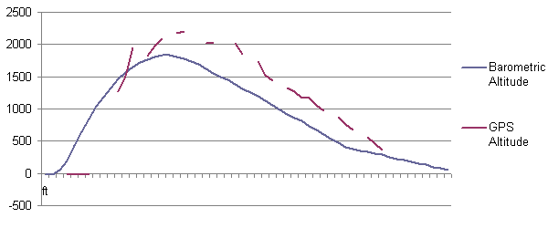
But, in the time it took me to get R1 launched, MaxStream came out with a new line of links, these guys have 30dB (1W) tx, and a -110dB rx, that are only 1.5" wide. So I ordered a few... Then hacked up a board, and launched. This time it actually worked! (the data from the launch is in a .zip file in the 2nd post)

But the 2nd launch I forgot to arm the recovery electronics in the rocket...:cry: At least now I have a really good Cd number for the rocket;)

In any case, I am now rebuilding...
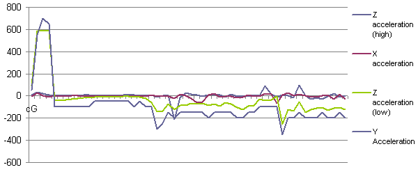
This time I am using the same GPS/downlink, but I have added a pic18f2550 processor, MMA2202EG +/-50G accelerometer (to measure the acceleration in the Z axis during the boost), LIS3LV02DQ 3 axis +/-6g accelerometer (for detailed logging or apogee calculation), MPXA4115A6U pressure transducer (for altitude monitoring), an array of 8 24LC512 .5mb EEPROMs to store data during the flight, 3 high current output channels (oepn drain so you can use a 2ndary battery for the igniters), a few uncomitted analog/digital I/O pins, and even a I2C bus (you don't need to know anything more than that it is really cool ;) ), and of course a bunch of blinky lights.

Once it is all working the project is going to be 100% open source, code, PCB layouts, etc will be available for download. If anyone is interisted I would be happy to build one for you. Right now it looks like the complete system is going to come in at a bit over $500.

Right now I am working on getting enough code written that I can prove that all of the parts will work happily together, which also makes it prime time to add more features.

Questions? Comments? Suggestions?
 
sounds like a great project. you don't shy from a challenge! put the project results (good and bad!) on your resume for college. good luck debugging all that. have you thought about how to bench-test and calibrate the accelerometers and software?
 
The sensors will be easy, since the +/-6g accelerometer has a completly digital interface, and comes precalibrated from the factory with way more accuracy than we will ever need, and I also have the GPS, which gives me a very accurate altitude refrence. Then after the first flight I can go and calibrate the analong accelerometer/altimeter ;) Although even without that I should be able to get pretty decent data, as I have a handy +1/0/-1G refrence tucked under the lab, and and a few calibrated pressure transducers in the junkbox.

The software is a bit more trickey, as it has explosive charges attached to it... For the first few launches I am going to have them set so that I can only fire them manually from the ground, using the handy serial uplink. And since all of my flights have an altimeter (apogee/800ftAGL), and a backup timer (apogee, fire the drogue so it at least doesn't bury itself), I am not sure I will ever set control of the 'chutes over to auto.

The biggest problem I have been having is the fact that I want to run at 100samples/second, and I don't have a multitasking operating system. So, anything that has to happen (say, reading coordinants from the GPS) has to happen in a very small window, or be split across several sessions.
 
GPS has come a very long way in the past few years, the chipset I am using is good to within +/-10meters. Well within the accuracy (especially when variations due to weather are considered) of the the altimeter. :)
 
Go for it. You'll really learn a lot of valuable skills if you can pull it off, or even if you give it a good try.

I switched from a EEPROM approach to using the Atmel dataflash, and it really helped my design. Check it out. At first I thought it seemed complicated with the buffers, but after trying to implement the EEPRROM approach, with its slow write times, I found that I was able to simplify the software quite a bit, besides being able to record a lot more data
 
I thought long and hard about using flash memory, but in the end it came down to a decision between performance/size. All flash memory (that I know of) needs a SPI interface, as opposed to the I2C bus that I am using for the gps/altimeter/etc. So I would have either had to add an extra 3 pins for the SPI bus, or convert the other modules to SPI parts which would cost me 4 extra pins due to the chip enables. At the time I made the decision I was working with a pic18f1220 and was very tight on pins, so that simply was not an options. Since I have upgraded to the pic2550 which has just enough pins to make it work, but I just don't see the point in wasting those valuable GPIOs on cheaper memory.

I got arround the 5ms write times associated with EEPROM memory by making an array of 8 chips, all with unique addresses on the I2C bus, so every cycle I can write a byte of data to each chip (at 400kbps, plenty fast) and let them finish their write cycles while I go and do something else. :D
 
I got arround the 5ms write times associated with EEPROM memory by making an array of 8 chips, all with unique addresses on the I2C bus, so every cycle I can write a byte of data to each chip (at 400kbps, plenty fast) and let them finish their write cycles while I go and do something else.

Good, creative solution there. I could have sworn I saw I2C versions of the dataflash, but I just checked, and I guess not. 4 mbits should be plenty of storage, especially if you're not trying to record multiple flights.
 
Ok, good/bad news...

The good...
I finished enough code that I could comfirm my plans were going to work, then moved on to the schematic, and then on to making a board layout, and etched a board.

The bad:
Cramming all of that technology onto a 2 layer board that is only 1.45" by 4" isn't easy... Even with .008" traces and an excessive amount of head scratching I ended up with a few really nasty jumpers--completly unaceptable.

The main thing that was taking up space is that EEPROM array (when I was designing it it didn't seem so big, but after spending a while laying out the rest of the board them SOIC eeproms look like small moons... So I think that in rev3.1 I will dump the EEPROM array, and my 3 GPIO pins, and add in some flash memory. The more I think about it, that I2C bus has way more power than the GPIO pins did, so it isn't that big of a loss...

In any case, I didn't give up on rev3.0, as this board will at least let me test if the altimeter/accelerometer/power supply/etc are going to work in unison, how sensitive to noise everything is, etc, etc.

So I broke out the iron and the transfer paper, and in the morning I had off from work (I had an orthodontist appointment at 9, so I told my boss I would be in at 1 ;) ) etched up a board. But of course 8mil traces and toner transfer don't really agree, so quite a bit of rework was needed on the board.

I should have an assembled board by wednesday (fingers crossed) and then I give myself a 50/50 chance that there will be some huge error that will prevent me from flying the board. In that case, I will start work in rev3.1 immediatly, have it sent out to batchpcb, and then work on more code using whatever works on the board I have now. If I get lucky and I can make this one work, I will probably end up flying him in about 2 months...

https://krazerlasers.com/images/schematic.PNG
https://krazerlasers.com/images/board2.PNG
 
Since no one here seems to be to interested in the project, I am just going to link its thread on the 4hv forums, which I am using as a way to keep notes until I get a decent web page written for it (hopefully soon!).

Scroll waaay down
 
Since no one here seems to be to interested in the project, I am just going to link its thread on the

I find your project very interesting - just WAY over my head since I don't know that much about what your doing. I always find it amazing that people can built stuff like this and wish I knew how. Of course you lose me about half the time since I don't speak the language. Don't get discouraged as I think you have a lot pf potential. I read some on your other forum about the rocket crashing into the playa. I know that must have hurt.

Harry
 
@ben, there PCB costs about $30 to fabricate, and there is about $100 worth of components on the board. The GPS costs about $70, and the Maxstream's are about $200 a piece (you need one in the rocket, and one on the ground). Overall, there is about $600 worth of parts for a full system. I am going to charge $100 for assembly, shipping, etc, which would bring the total for a shippable to about $700.

The easiest place to cut costs would be to swap out the XT-09 modem for something cheaper, especially since most people don't need the full 40 mile range. I need to break out my Xecom modems (.5w tx, -100dB rx, $80 a piece), and see if I can get them to start working, as that would bring things into the range that I could ship one for $500. But that isn't going to be until I at least test out this rev, which hopefully will be the 2nd weekend in October.

@shotoneup, The key is to break it down into a bunch of tiny little modules, and work on all of the parts as individual assemblies. And a lot of time allocated;) for debugging
 
GPS has come a very long way in the past few years, the chipset I am using is good to within +/-10meters. Well within the accuracy (especially when variations due to weather are considered) of the the altimeter. :)

Which GPS are you using? I thought most GPS units could only sample about once per second...
 
Which GPS are you using? I thought most GPS units could only sample about once per second...

depends what you get, and how you set it. Beeline GPS you can set to sample every 15sec. or every .5 second (or faster I think)

Ben
 
I am using a Lassen IQ GPS, which updates the GPS data once per second. The GPS chipset that I know of that samples faster than that is the ETek, which came out after I bought the IQ. I was considering implementing it in the rev3.2, however it costs more (although an extra $20 out of like $500 isn't that bad), but also it would be a huge pain to interface into the existing scheme of things.

And in any case, the overall idea was to use the GPS mainly for a absolute position reference to find the thing (so 1hz update rate is more than enough), and then use the on board sensors for the main high speed data logging.
 
Development for the rev 3 of the tracker is now dead, mainly because the one and only prototype is laying out in the mojave somewhere :cry:

Some exellent data was taken before the poor things demise, see its webpage and Krazed III's page for all of the graphs and zips of the flight data.

One typical flight's data is shown here:
Altitude data:
altitude_1.PNG

Accelerometer data:
acceleration_1.PNG

(not that these graphs were made with the 1hz data sent down the uplink, because I never had time to get data stored in the flash memory--that should be working by the time I fly rev4 this fall Also the altitude hasn't been calibrated yet, and it reads about 10% low)
 
Back
Top