Testing for Hobby-Accessible Ablative

The Rocketry Forum

Help Support The Rocketry Forum:

This site may earn a commission from merchant affiliate links, including eBay, Amazon, and others.

CCotner

Well-Known Member
Joined
Sep 4, 2012
Messages
888
Reaction score
3
Hi! I am announcing that in the next few days we will be conducting a somewhat crude ablation rate test. The test setup is illustrated in the following Drawing; we are basing it off of existing scrap material and some static test hardware that we have lying around in the Experimental Engineering class lab.

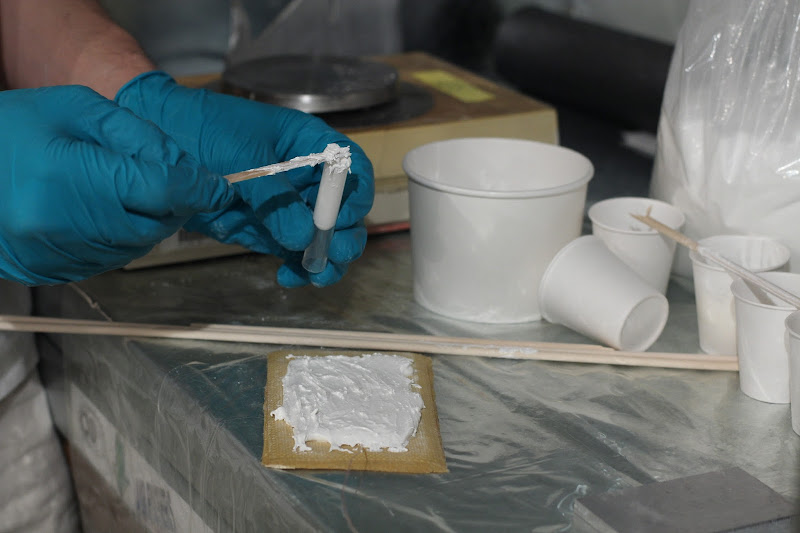
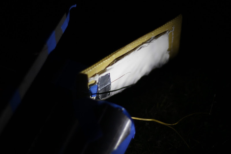
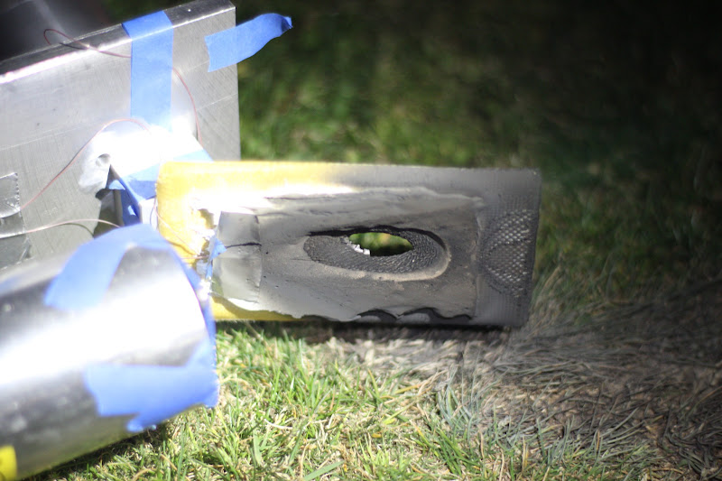
The ablation target will consist of a .125" thick laminate of plain-weave 5.6oz Kevlar, with 300F post-cured PTM&W 5712 epoxy. This is our current nosecone wall design for Bare Necessities, at least the structural part. On top of the Kevlar is a .25" thick layer of our test ablative. The ablative mixture ratios will be determined partly by workability when we do the ablative layup later this week, but the base will be a laminating epoxy, either Aeropoxy 2032/3660 (Tg, and presumably T_ablation, of ~200F) or partially post-cured PTM&W 5712 (with a Tg/T_abl or ~275F). The advantage of using a lower Tg epoxy as the base than the underlying structure is that it limits the temperature rise of the entire assembly to the ablation temperature of the ablative, protecting the underlying structure. The additives to make ablative will be ~25% by mass (~25% of the epoxy mass) TiO2 powder (for infra-red opacity), and then glass hollow microballoons to the perfect-packing state (about 3:1 by volume). The final material when mixed will be a thick dry paste.

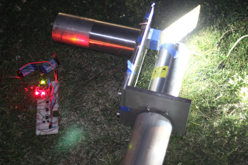
The ablator (so to speak) will be an Aerotech I49N motor. This was chosen because of the high exhaust velocity, very low metals loading (clean burning exhaust), and long burn time/low thrust (meaning we don't have to reinforce the existing frame or the sample). The sample will be placed at a 30 degree angle to the motor, as shown in the image, and the impingement point (center of the exhaust jet) will be directly over the center of the sample. We have 2; we will probably fire both in series, unless the ablation rate is extremely high.

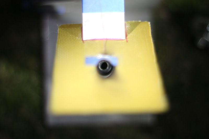
For data collection, a trio of Type-E 40Ga thermocouples will be recording at a few kHz on our shiny new class dataloggers (16-channel, 16-bit, 300kS/s (kHz)), along with a CJT (linearized thermistor). One will be on the surface of the ablative; one will be at the bottom of the ablative; and one will be at the back side of the laminate. All will be directly underneath the target point. We expect the first one to be destroyed. Finally, a GoPro Hero 3 Black will be a few inches away (or the minimum focus distance away), recording at 480p and 240FPS. One of us will also probably video-record the process at 720p and 60fps on a tripod from our DSLRs (using a telephoto lens), and possibly take stills as well.

As the results of this experiment will likely be useful and interesting for others on this forum with an interest in pushing composite rockets past Mach 3, we will try to post our results here in a somewhat-timely manner.

View attachment AssemblyDiagram.PDF
 
Very cool! FWIW, we used an epoxy compound with asbestos in it (prolly unobtainium now) and cork sheets as ablative material for the Atlas nosecones. It was primed and prolly coated with dinosaur snot by the paint dept. so it would look pretty for the press.
 
Very cool! FWIW, we used an epoxy compound with asbestos in it (prolly unobtainium now) and cork sheets as ablative material for the Atlas nosecones. It was primed and prolly coated with dinosaur snot by the paint dept. so it would look pretty for the press.

I don't know if you can answer this, but how long was the asbestos fiber? Was it there to give the ablative some structural integrity? Should we include a small percent of loose short-chopped glass fiber in ours to reduce the chance of cracking?
 
Oh, buddy that was a few beers ago. I think it was a compound by Hysol we bought commercially by spec. Grey in colour. It was primarily to bond the cork insulation pads over the honeycomb structure made by Hexell. IIRC it had .020 alaly bonded to the exterior surface acting as a heat sink to ambient inside the cone,tehn epoxy, then cork, then primer and finally paint. We retrieved one from a bad shot and there where severe scortching marks at the max q points, but no burnthru of the charred cork. Monocoque structure with stiffening ribs w/explosive bolts to get rid of it once we cleared boost thru the atmosphere. Not sure if the glass fibres would act as heat conductors or bonding agent. No help here, sorry!
 
Last edited:
Knowledge of the Tg, or glass transition temperature, is interesting, but I fail to see how it is useful as a predictor for ablation. It may be useful for predicting when the surface will be succeptible to slump under sufficient pressure and time, but that isn't quite the same situation the nosecone will be encountering - particularly the timeframe portion.

I would think that perhaps what is wanted is something with a moderate melting point and low thermal conductivity, or something which forms a char layer which acts as an insulator. But of course I could easily be wrong!

I'd be looking to see if there is a way to use Calcium Silicate, balsa, chalk, cork, cotton, wool felt, paper, polyurethane foam, some types of sugar, etc

A funny one would to be to make an outer surface of the nosecone from something like end grain oak (grain oriented perpendicular to direction of flight) and saturate with water before launch. Steam has a low coefficient of thermal conductivity and limits the internal temperature to that of boiling water for as long as water is present. Oak is ring porous and will allow the steam out quite possibly without cracking, and oak should form a char layer when it runs out of water. Oak is even not all that bad an insulator.

Anti-freeze of various forms may work better than water for this application. One could choose a non-flammable liquid and use its boiling point as a control for the internal temperature, at least for the time it is present. The quantity of liquid and the heat of vaporization would supply the degree of heat that could be carried away in the first phase of insulation of such a system. The second phase would be characterized by surface char and I expect that would be harder to predict.

Or one could get more sophisticated and use a pump to supply a liquid under pressure to the tip of the nosecone, so it boils away on the outer surface of the rocket. Perhaps having the tip be a high conductivity metal with a small hole at the top or a ring of holes at the bottom, and filled with something like water...

Sorry for rambling; just sort of thinking out loud. Not enough sleep the last few days.

Gerald

From our research we have determined that the insulation of the microballoons is likely to isolate the heated surface well enough for the top layer to slough off without the parts underneath weakening too much. Or so we hope. That's what the test is for.

The last idea you came up with, though, is actually basically what CCotner is doing for his research boosted dart project. He can go into more detail on that, though.
 
To add some detail; we chose a material that will not form a char in an effort to have a smooth surface after the ablation. The hollow microballoon layers will (hopefully) shear off as the surface reaches the glass transition point or slightly higher, exposing cool epoxy underneath.

My research project is a water-cooled Mach 7 boosted dart (52kNs disposable booster with .95 mass fraction) for hypersonic data recovery. I don't know mow much more I can say on the forum; I need to work out a proper NDA with my research advisor. We plan on flying that this summer; it is unlikely that it will fly at anything other than a military installation, though.
 
If you are using glass microballoons, then the result will be to sandblast the fins. If the phenolic, then a char layer might form.

Gerald
 
I've used alumina ceramic putty, good to 2300 F. If that's not enough, the zirconia is good to 4000 F. https://www.mcmaster.com/#ceramic-adhesives/=lvlpz7

How do you use it? Thin layers?

How insulative exactly is it? From what we've researched, microballoons are basically the best insulation, and using a low-temperature epoxy would make the surface ablate. Survival of the coating material isn't necessarily what we want, since we primarily want to ensure that the nosecone layup doesn't exceed 300 F, and we spend a loooooong time (~15 seconds) with stagnation temperatures well in excess of that, and peak temperatures of ~1500 F. If the surface doesn't strip off, then heat would just be able to soak through.

But we'll see what happens with our ablative, probably tomorrow.
 
How do you use it? Thin layers?

How insulative exactly is it?
It's a reasonably good insulator. I used it as a nozzle extension and it was undamaged after a 10 sec burn. Underlying fiberglass was undamaged (1/4" thick tapering to about 1/16"). You can have a 4 oz tube in a couple days to test it. Wet consistency is about like toothpaste.
 
If you are using glass microballoons, then the result will be to sandblast the fins. If the phenolic, then a char layer might form.

Gerald

I think the fins will probably not be harmed by the subsequent sandblasting. It'll be cool to see if the damage is visible, though.
 
I've used alumina ceramic putty, good to 2300 F. If that's not enough, the zirconia is good to 4000 F. https://www.mcmaster.com/#ceramic-adhesives/=lvlpz7

Do these really follow an ablative model? This stuff is made to stay in place and is likely fairly heavy, inhibiting performance. What you want is a substance or laminate that will erode evenly and sacrificially disentigrate without affecting the aerodynamics and doing so on a time base, that by the time it is gone, the underlying structure survives.
 
Another concern is RF-transparency. We know for a fact that TiO2 and microballoons are sufficiently RF transparent, but we'll probably test some of that paste anyway.
 
Another concern is RF-transparency. We know for a fact that TiO2 and microballoons are sufficiently RF transparent, but we'll probably test some of that paste anyway.

Ceramics tend to be pretty RF transparent. I don't have personal experience with alumina or zirconia in this regard (ask me about BN sometime!), but for the most part RF waves are only significantly attenuated by conductors. Dielectrics in general don't do much to RF waves, especially if they're thin. A ceramic coating isn't going to ablate - hydrocarbons are the most popular choice for ablatives since you're relying on pyrolysis of the surface to create that cushion of cool gas and hydrocarbon-based solids are usually nice, big molecules that give off lots of little gases when they pyrolize.

15 seconds really isn't that long - not in the 'stuff burning up the atmosphere' scheme of things, anyway. Is weight critical enough that you can't use metal at all in the nose? For a duration that short you may be able to get away with a refractory nose tip (moly, tantalum, niobium may work, tungsten can take more heat but is a beast to fabricate) and make the rest of the nose from something less exotic like Titanium.

In a related vein to the short duration, how about a cast ceramic tip? You can relatively easily find casting compounds which have properties nearly as good as solid Zirconia. (Blatant advertisement: www.aremco.com is a good place. I've used their potting compounds before and they worked really well). You may want to stay away from alumina - this is a high-heat-flux situation, and alumina isn't good in thermal shock. A paste or casting compound may be okay, but zirconia-based compounds are available anyway, and that usually works pretty well. Alumina is also pretty thermally conductive - better than stainless steel. You may be able to stay away from an ablative by simply using something nice and insulating (like Zirconia) to keep the heat out long enough for it to pass back below Mach where you don't have a problem any more.

I hope you're using a fairly high-frequency transmitter, though - at least a couple hundred megahertz. You're gonna get some plasma at mach 7 - not much, but it'll be there - and you don't want to lose communications because the rf energy hits an ionized brick wall.

And don't forget to paint it black!
 
Zirconia ceramic isn't a terrible idea, i didn't know much about ceramics when the project started.

To be clear; the primary application of this is for the N5800. The Mach 7 vehicle is a different project; it is primarily an excercise in liquid cooling, not ablation.

One potential problem with a non-ablative (high temperature ceramic layer painted on the kevlar shell) thermal protection system (TPS) for the N5800 is that it must also be highly insulative to prevent heat soak from weakening the 300F epoxy underneath it. I'd like to keep the core structure below 150F for the entire flight.

As far as coloring, while I understand the need for radiative cooling, it's going to end up all white, because of the titanium dioxide. The sizeable difference in pre-launch temperature might almost make up for the difference in radiative cooling!

The tip stays copper for the N, because we need the noseweight for our micro-sized fins.
 
I appreciate the pretty interesting suggestions for the mach 7 vehicle (we are strongly considering a tungston tip on the water-cooled copper shell nosecone), but I'm especially in seeing if the microballoon/TiO2 ablative works as well as our research suggests it should.
 
Have you considered a boron nitride tip? You should check out the NASA AMES & JSC Arcjets. Very cool, we used them to qualify shuttle tiles and RCC panels.
 
Laid up the thermocouple under a nice blanket of microballoons...

First I mixed one pump of Aeropoxy PR2032:p
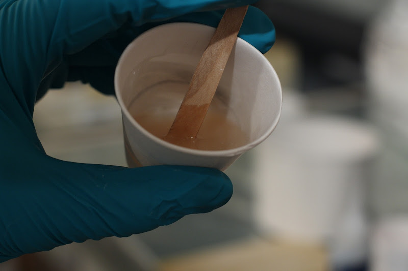
H3660. Not quite a pump, actually, but I ensured that the mixture was perfect by weight. That was 26.09 grams. In the photo it looks cloudy because there was some TiO2 on the mixing stick I used.

IMG_3154.JPG


Next, I added in a 1:3 mass ratio TiO2. That meant 8.64 grams of TiO2. This is to opacify the ablative to IR and visible radiation and hopefully thereby reduce conductivity.

IMG_3155.JPG


Then, I added in a 2:1 volume ratio (the highest I was willing to do for workability) 3M 01-14600 glass bubbles. That turned out to be 6.6 grams of these particular microballoons. The photo shows it at a 1:1 ratio before being mixed.

IMG_3153.JPG


Then, I applied it to our Kevlar panel, which you can see just above this. To prep the panel, I first sanded the peel ply surface lightly with 60-grit sandpaper. I then cyanoacrylate'd a 40-gauge type E thermocouple to the center of the panel, and sanded off all excess CA around the thermocouple itself. I checked the resistance through the junction after CA'ing it, and it remained the same as before, indicating that the contact wasn't affected by the superglue.

Above the panel, you can see me packing some excess ablative I had left into a tube so that we can measure the resulting density.

IMG_3152.JPG


No, it's not cake icing, but it looks and feels just like it.

IMG_3154.jpg
 
To add some detail; we chose a material that will not form a char in an effort to have a smooth surface after the ablation. The hollow microballoon layers will (hopefully) shear off as the surface reaches the glass transition point or slightly higher, exposing cool epoxy underneath.

My research project is a water-cooled Mach 7 boosted dart (52kNs disposable booster with .95 mass fraction) for hypersonic data recovery. I don't know mow much more I can say on the forum; I need to work out a proper NDA with my research advisor. We plan on flying that this summer; it is unlikely that it will fly at anything other than a military installation, though.
Below is a plot of aeroheating that is experienced as a function of velocity and altitude.
aeroheating plots.jpg

The stagnation point heating at Mach 7 is ~3 kw/cm2 on the deck and ~2 kw/cm2 at 15 kft. For transpirational cooling the water flow rates needs to exceed 1 g/cm2-s.

I'm not aware of any dart hitting Mach 7. The only missile system I'm aware of with that level of performance was the Sprint ABM that would do 0 to Mach 10 in 5 seconds with an acceleration of 100 G.

[YOUTUBE]msXtgTVMcuA[/YOUTUBE]

The HIBEX missile accelerated even faster, initially at 400 G and reached Mach 7 in 1.1 second at an altitude of less than 1 mile! It was a tiny missile.

HIBEX.jpg

Bob
 
I think we are going a bit off topic...

That said, when this is cured tomorrow, I will sand it down to uniform thickness, attach the thermocouples, and load the motors.
 
I'm not aware of any dart hitting Mach 7. Bob

Perhaps you will be soon. :) TO be fair, though, Mach 7 is the optimistic end of our estimates. More realistic estimates put it closer to Mach 6. The big difference is mass. But yes, off topic.
 
I build high performance, supersonic, composite radomes for a living. Our material of choise is V376, an IsoQuarts with a cyanoester prepreg. It's typically postcured at 400degF but there is a varient that postcures at 600degF. For what we do RF transperency is a top priority.
Also, about a year and a half ago we did some ablaitive work for target rockets. Basically bonded cork to the aluminum fin can and nose cone (all the black in the photos) and sealed it with a silicone based paint made by Pyromark. Good to 1200degF.

001.jpg

On-the-rail-A.jpg
 
I think we are going a bit off topic...

That said, when this is cured tomorrow, I will sand it down to uniform thickness, attach the thermocouples, and load the motors.

Perhaps you will be soon. :) TO be fair, though, Mach 7 is the optimistic end of our estimates. More realistic estimates put it closer to Mach 6. The big difference is mass. But yes, off topic.
Our company developed and manufactured the highest temperature ceramic of use in an oxidizing enviroment that exists for use as the combustion chamber liner for Mach 7 sacramjets, and I performed the qualification tests where we simulated the complete 7 minute flight profile multiple times on the same sample so I have a bit of testing experience here. :cool2:

If you want an ablative coating, you can go to Dow Corning and buy it, however you really are in the heating range where you need carbon-carbon and employ radiative cooling as well as ablation. Cotronics graphite furnace cement might work for short times, but these conditions are challenging. Think reentry materials.

My previous post is not "off topic" as it was meant to illustrate the extent of the heating obtained in this flight profile. You will note in the video that the flight vehicle glows white which means the surface temperature is well in excess of 2000 K. At a minimum, in that time period, they were using silica phenolic ablative nose cones.

You're going to need an optical pyrometer to measure the temperature of the exposed surface which will be essential to analyze your results. If you could simulate the energy loading with a motor (which I don't believe you can with your solid rocket motor) your surface temperatures should be in the 3500-4000K range if it survives. If you plan to video the event, get a ton of neutral density filters and keep adding them until you can collect a good video of a light bulb filament which is approximate the same temperature that ablator surface will reach. :dark:

It will be a good learning experience.

Bob

What I meant by off-topic was while the discussion is interesting and productive, it's getting out of the easily-hobby-accessible level, and above the level of Bare Necessities, that the thread is about. Anyone can trivially get Aeropoxy, titanium dioxide, and glass microballoons.

I do understand that the solid motors we are using won't reach the temperatures that CCotner's dart will experience, but it's our hope that our (also hobby-accessible) testing will be better able to approximate Bare Necessities' flight profile. I do agree regarding our experiment it would be better for measuring surface temperature if we had a pyrometer, but we simply hope that the thermocouple on the top will suffice (and survive at least the initial part of the burn).
 
Last edited:
I suggest you look up AVCOAT. It was the Apollo heat shield and would have been used for the Orion heat shield. Novalac epoxy and nomex honeycomb is no harder to find and will work a lot better as well. So will a simple 1/8" thick graphite epoxy layup with 12-14 layers of 3K cloth. The graphite epoxy ablation rate should be in the 10-20 mils/second range. I'm guessing the Kevlar composite will ablate at a significantly faster rate.

Bob
 
Before. We decided not to care about voids too much because this would be a worst-case test. On the real deal I'll pull a vacuum to get all the bubbles out.
IMG_3185.thumb.jpg


The back side of the test panel.
IMG_3186.thumb.jpg


This is the front of the test panel with the thermocouple on it.
IMG_3187.thumb.jpg


We taped a thermocouple to the back.
IMG_3188.thumb.jpg


Here's our test setup. I have a data logger on the left with instrumentation amplifiers to get data from the thermocouples. The shiny cylinder contains the I49, and the brightly lit parallelogram is the ablative-coated kevlar panel. The other aluminum cylinders are weights to keep the test stand from moving.
IMG_3191.thumb.jpg


Here's a closeup of the panel, about to face its destiny.
IMG_3192.thumb.jpg
 
AAAAAAAAND the results.

[YOUTUBE]jiNXDruZfjQ[/YOUTUBE]

1/8 speed, up close.
[YOUTUBE]LEklsGHIhh4[/YOUTUBE]

Motor 1, ablative 0.
IMG_3194.thumb.jpg


The hole was actually fairly small.
IMG_3195.thumb.jpg


IMG_3196.thumb.jpg


Here's a closer look.
IMG_3197.thumb.jpg


Based on the video, it's clear that the extremely high-velocity, high-density, high-temperature, still-reacting exhaust gases in the exhaust stream easily overwhelmed the ablative. In the slomo video, you can see the test rig shift when it finishes burning through the panel as a whole, which was 1 second in. The motor burned for just over 6 seconds overall, just like the I49 I flew back in December.

However, the ablative clearly protected well against the slipstream around the motor, which was not quite as hot, not quite as fast, but still very damaging. We're not quite decided on what we're going to do yet; we are planning on doing another test with the ceramic adhesive that Rocketjunkie suggested.
 
Back
Top