Graphite Signal Attenuation

The Rocketry Forum

Help Support The Rocketry Forum:

This site may earn a commission from merchant affiliate links, including eBay, Amazon, and others.

Marsman

Well-Known Member
Joined
Feb 24, 2009
Messages
167
Reaction score
0
What are people's experiences building with the Performance Rocketry Graphite-infused Profusion G12? My main concern is if it's going to attenuate my tracker (Telemetrum) signal (both the GPS lock and the transmission) too much after being inside of a profusion coupler and profusion airframe. I'd like to try out the profusion G12, but might switch back down to regular G12 or G10 if the signal issue is too much. I can't put the telemetrum in the (probably graphite anyway) nose cone for a number of reasons.

The application is a 75mm shot to 37-40,000 ft and Mach 1.8.
 
What are people's experiences building with the Performance Rocketry Graphite-infused Profusion G12? My main concern is if it's going to attenuate my tracker (Telemetrum) signal (both the GPS lock and the transmission) too much after being inside of a profusion coupler and profusion airframe. I'd like to try out the profusion G12, but might switch back down to regular G12 or G10 if the signal issue is too much. I can't put the telemetrum in the (probably graphite anyway) nose cone for a number of reasons.

You will be fine transmitting out of it -- it's similar to the fiberglass+"graphite infused" epoxy composite as the proline nose cones are made from. By the same token, however, I don't really see what the "profusion" is buying you from a strength perspective; in a composite, the strength comes from the fibers (still glass, in this case), rather than the matrix material -- the graphite powder basically serves to dye the layup, and that's about it. For my cash, I'd buy G10 tubes (convolute fiber direction FTW) and color them with a black Sharpie. You'll get nearly identical results and have beer money left over.

(If anyone has done compression/bending tests comparing Profusion v G12, I'd love to see them BTW. The above is speculation based on my experience. Is Doc still accepting parts for rocketmaterials.org?)

The Rocketry Warehouse site mentions different wind angles for the profusion tubing, with more axial fibers that should help the tube bending strength to prevent shreds. If that's accurate, it's worth something.

Improving the heat resistance, strength, or stiffness of the resin would help the overall composite strength, because the failure mode is usually local buckling in compression, and stronger resin would help there. But there's no way to tell what, if any, improvement to the resin properties are provided by the carbon dust for the profusion version.

I know that the profusion nosecones don't have nearly the RF attenuation that carbon fiber nosecones do. But I haven't done tests to see if the RF effect is zero or just near-zero.
 
The Rocketry Warehouse site mentions different wind angles for the profusion tubing, with more axial fibers that should help the tube bending strength to prevent shreds. If that's accurate, it's worth something.
Oh, cool, I missed that, thanks! That would indeed help when compared strength-wise with the standard G12 wound material.
 
Does anyone have more information with respect to Profusion nosecones and RF attenuation? Looking at a nosecone but want to be sure the tracker signal will not be affected by the graphite.

Thanks for the help, Scott
 
One way around this would be to do a bulkhead SMA connector and use a bulkhead mount antenna that gets "exposed" with the apogee deployment. I purchased a spring antenna for 400Mhz a year ago with an SMA connector similar to this one:
https://www.ebay.com/itm/Golden-Sof...237?pt=LH_DefaultDomain_0&hash=item2c79c2758d

Sheeee-oot I bought an SMA version of the above antenna a year ago and they aren't available now. You could put an extension cable on a bulkhead mount and ziptie it and an antenna along the apogee shockcord as an alternative.

The only disadvantage here is that you may not have an Rf link on the "upside" of the launch. The telemetry would only be available with the apogee deployment and exposure of the antenna outside of the rocket body. If you are using
deployment electronics that are going to record the flight anyways that might not be as much of a problem as you can download after recovery. If you consider the GPS as a recovery tool so you can "get" the rocket for download that might
be a reasonable tradeoff for using the advantages of a graphite airframe. Kurt
 
Does anyone have more information with respect to Profusion nosecones and RF attenuation? Looking at a nosecone but want to be sure the tracker signal will not be affected by the graphite.

I had a customer at BALLS use the black fiberglass tubing from Rocketry Warehouse that has graphite in it. It assume that means it was Profusion. It was not a carbon fiber tube. It was a 54mm tube with the transmitter mounted inside. It significantly attenuated 900MHz and he had trouble tracking his flight. Post flight we did a quick test by looking at the received signal strength with the transmitter antenna inside and outside the tube. The difference was huge. I don't remember the exact number but I think it was in the range of 30dB. I do not recommend graphite tubing or graphite nosecones for use with TelemetryPro transmitters. The range will be drastically reduced.

On a side note, I would be interested to find out if a sample of the material in question gets hot when placed in a microwave oven. I expect it would. That might be an easy way to determine if that or other material is RF transparent. However, I have never tried it myself.
 
Any composite with significant carbon in it will provide major amounts of RF attenuation. Carbon based composites are being actively studied as purpose-designed RF shielding. I just looked at a few abstracts of papers...one pointed to an attenuation in the 2-18GHz range of 16 dB in 1mm of material, so VernK's number of 30dB would seem plausible for typical rocket tube dimensions. The shielding effects increase as you go from carbon powder -> carbon fiber -> nanotubes -> graphene. Personally I would not put an antenna inside any structural component with ANY carbon in it.
 
I had a customer at BALLS use the black fiberglass tubing from Rocketry Warehouse that has graphite in it. It assume that means it was Profusion. It was not a carbon fiber tube. It was a 54mm tube with the transmitter mounted inside. It significantly attenuated 900MHz and he had trouble tracking his flight. Post flight we did a quick test by looking at the received signal strength with the transmitter antenna inside and outside the tube. The difference was huge. I don't remember the exact number but I think it was in the range of 30dB. I do not recommend graphite tubing or graphite nosecones for use with TelemetryPro transmitters. The range will be drastically reduced.

On a side note, I would be interested to find out if a sample of the material in question gets hot when placed in a microwave oven. I expect it would. That might be an easy way to determine if that or other material is RF transparent. However, I have never tried it myself.

I believe RW kits nosecones are radiolucent and black colored fiberglass. I have a Dominator 4 v1 (from Proline) that has the profusion body tubes but the term profusion is not attached to the nosecone. If anyone knows otherwise, please chime in.

Kurt
 
Thanks for the info everyone. Looks like I better not chance it.
 
I would bet they would send you a short piece to try for a reasonable price if you asked.

Kirk
 
One way around it if one already has the parts, is jury mount the tracker inside and do a range test. Get in an open area and test it. Got good range? In good shape then. Kurt
 
I have to say I have NO idea where Wildman gets the tubes from. But I can say that I had no issues with a tracker in the black nosecone that came with my Wildman Mini.

Kirk
 
I strongly recommend that you actually test what the attenuation is. If you have a receiver with a signal strength meter, you can set your transmitter at a convenient distance away from the receiver and record the signal strength. Repeat the measurement with the transmitter inside the rocket.

If you have a wireless modem type of transmitter and a smart phone, you should be able to measure this directly using one of the wifi-finder aps on the cell phone. The signal strength in db is displayed as well as the operating channel, so it really is trivial to do at 2.4 GHz. The attenuation is frequency dependent, so you don't need to use you actual hardware to do the measurement. Any transmitter/receiver combination will work as you are simply looking for the relative attenuation.
From https://www.moonblink.com/store/attenuation_at_24ghz_.cfm
[h=3]Radio Wave Attenuation at 2.4 GHz[/h]Radio waves don't travel the same distance in all directions. Walls, doors, elevator shafts, people, and other obstacles offer varying degrees of attenuation, which cause the Radio Frequency (RF) radiation pattern to be irregular and unpredictable. Attenuation is simply a reduction of signal strength during transmission. Attenuation is registered in decibels (dB), which is ten times the logarithm of the signal power at a particular input divided by the signal power at an output of a specified medium. For example, an office wall (i.e., medium) that changes the propagation of an RF signal from a power level of 200 milliwatts (the input) to 100 milliwatts (the output) represents 3 dB of attenuation.

The following provides some approximations of the attenuation values through common office construction at 2.4 GHz (802.11b/g):

  • Plasterboard wall: 3dB
  • Glass wall with metal frame: 6dB
  • Cinder block wall: 4dB
  • Office window: 3dB
  • Metal door: 6dB
  • Metal door in brick wall: 12.4dB
Other factors that can effect the range of an RF signal at 2.4GHz include concrete fiberboard walls, aluminum siding, pipes and electrical wiring, microwave ovens, and cordless phones.

Carbon fiber and other conductors will attenuate 2.4 GHz signals, and 1.57 GHz GPS signals. The amount of attenuation will depend on percentage, particle size and/or fiber length. Since GPS signals are very weak, attenuation of any kind may degrade or eliminate coverage. A transmitter signal attenuation of 3 db reduces the effective transmitter by a factor of 2. A 6 db attenuation is a factor of 4 power reduction and reduces the transmitter range by a factor of 2 which can be significant if your signal strength is borderline to be with.

https://www.faa.gov/about/office_or...o/service_units/techops/navservices/gnss/gps/

Bob
 
If you use a fiberglass nose cone with a metal tip instead and have the tracker mounted upwards (antenna facing the tip) you will experience minimal attenuation. The metal tip is in the "dead zone" of the antenna, so it has little discernible effect on the range as long as you have a few inches between the end of the antenna and the tip.
 
If you use a fiberglass nose cone with a metal tip instead and have the tracker mounted upwards (antenna facing the tip) you will experience minimal attenuation. The metal tip is in the "dead zone" of the antenna, so it has little discernible effect on the range as long as you have a few inches between the end of the antenna and the tip.

In the old R/C days one was always told never to point the tip of the antenna "at" the flying airplane at distance as more likely to have a control glitch. Kurt
 
I wonder how much the new metallic paints attenuate the signal. I now the old ones had a lot of metal in them, not sure what's in the new ones....
 
I wonder how much the new metallic paints attenuate the signal. I now the old ones had a lot of metal in them, not sure what's in the new ones....


Ahhhhhhh, rattle can Rustoleum dorked 70cm signals from a Beeline GPS. Not once but twice. The one rocket core sampled when the apogee charge was mis-connected so the BLGPS was trashed. Other rocket came down within sight so it was recovered though only one packet at altitude through a Yagi antenna'ed receiver. I wouldn't trust "ANY" metal paint unless one wants to take the trouble of doing detailed "tests" with a dedicated test article.

Interesting aside though is when the surviving, recovered BLGPS was downloaded, it did have a very valid .kml file with 6 to 10 satellites locked through the course of the flight. So, the bay was opaque to the 70cm transmitted Rf but "clear" to the incoming GPS signals. For the unfamiliar, the BLGPS will store position packets in memory for later download. Can store packets at a 1/sec refresh rate as opposed to the once every 5 seconds transmitted via APRS Rf.

My next project was a Wildman Jr. that was already painted metallic red. With such a small rocket, I simply stripped the main chute bay of the offending red and shot a "plain jane" yellow. Rocket Rf tracks fine with an H/T antenna.

The attenuation is dependent with the several factors Bob mentions above and can be unpredictable. The simple answer is to avoid metallic paints for a tracker bay period. Or have some sort of external antenna such as something like a bulkhead mounted antenna that is "exposed" when the apogee charge fires. Only caution here is if there is an apogee failure, one might not get an approximate location of the "death dive" if the rocket portions don't separate. Kurt
 
That might happen because the metal flakes are spaced relatively far apart, close enough to cause issues with 70cm but far enough apart for the 1.575 GHz GPS signals to get through. I'd be willing to bet if you tried the flight again you wouldn't get the same result, though... very unpredictable.
 
That might happen because the metal flakes are spaced relatively far apart, close enough to cause issues with 70cm but far enough apart for the 1.575 GHz GPS signals to get through. I'd be willing to bet if you tried the flight again you wouldn't get the same result, though... very unpredictable.

No way Jose' am I going to try that again. Launched two different rockets that day with same brand of metallic paint and I'm not into a
tracker that does "now you see me, now you don't routine".:grin: I wanna find 'em, get back and fly some more. Not be triapsing about looking. When flight opportunities are at a premium, best to cut the recovery time as much as possible.:wink: I'll stick to non-metallics on tracker bays and nosecone carriers or fly the bay bare. Kurt
 
Last edited:
If you use a fiberglass nose cone with a metal tip instead and have the tracker mounted upwards (antenna facing the tip) you will experience minimal attenuation. The metal tip is in the "dead zone" of the antenna, so it has little discernible effect on the range as long as you have a few inches between the end of the antenna and the tip.

In the old R/C days one was always told never to point the tip of the antenna "at" the flying airplane at distance as more likely to have a control glitch. Kurt

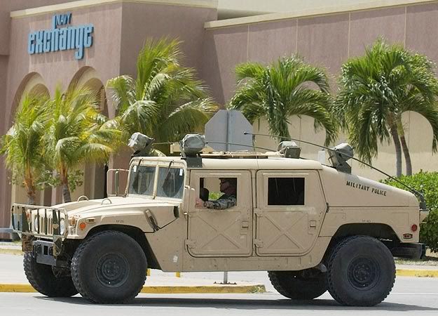
That's because the typical vertical antenna radiates mostly perpendicular to the antenna with little (in theory 0) radiation from the tip of the antenna. A trick din communication when you need to communicate from a vehicle both ground station and aircraft is to use a long whip antenna (multiple wavelength) and bend it over so that a fraction of the antenna is parallel to the ground. The alters the radiation pattern so that it is more overhead. You will notice this in military convoys where the communication Humvees have the rear mounted antennas bent over forward. It not just to keep it from hitting overhead obstructions.

hummer-625x450.jpg


Bob
 
FYI:

Been using Falcon trackers for years.....219.586..etc & 223...224 freq's
Many of my rockets are heavily coated with Rustoleum interior/exterior Blue & silver metal flake. Never had any issues in this freq. range.
I tested first by placing in bay and out of bay, taped to mailbox and checked with receiver from 1/2 mile away. Barely perceivable difference.
No difference between bays painted with regular or metallic paint.

Hmmmmm, that would make for a small market for a 1.25 meter (220Mhz frequency) APRS GPS tracker. Yeah, only good for the ham radio folks but if ya' wanna have metallic paint AND a GPS tracker would be a reasonable alternative. I freely admit
I'm a GPS weenie as opposed to RDF' ing it. Don't trust my skills even though my limited practice shows my offset attenuator is more than adequate to get good bearings up close. Of course, the falcon trackers are very small size. Kurt
 
Last edited:
It's not just metal flake and metallic paints. I had severe attenuation from yellow paint on one nosecone. To the point where a handheld with rubber ducky would not reliably pick up the BRB beacon from away cell distances even when the rocket was not on the ground. I had a beam though, so no issues at the flight ranges for that rocket. But I won't be using that (or other) yellow paint on nosecones again!

Bending the antenna over for HF communications as on military vehicles probably converts it to an NVIS antenna (Near Vertical Incidence Skywave). This changes the skip distance to much closer than would normally be the case for a near ground vertical antenna, reducing the communications distance down to a few hundred mile range and substantially attenuating longer range signals.

Gerald
 
Back
Top